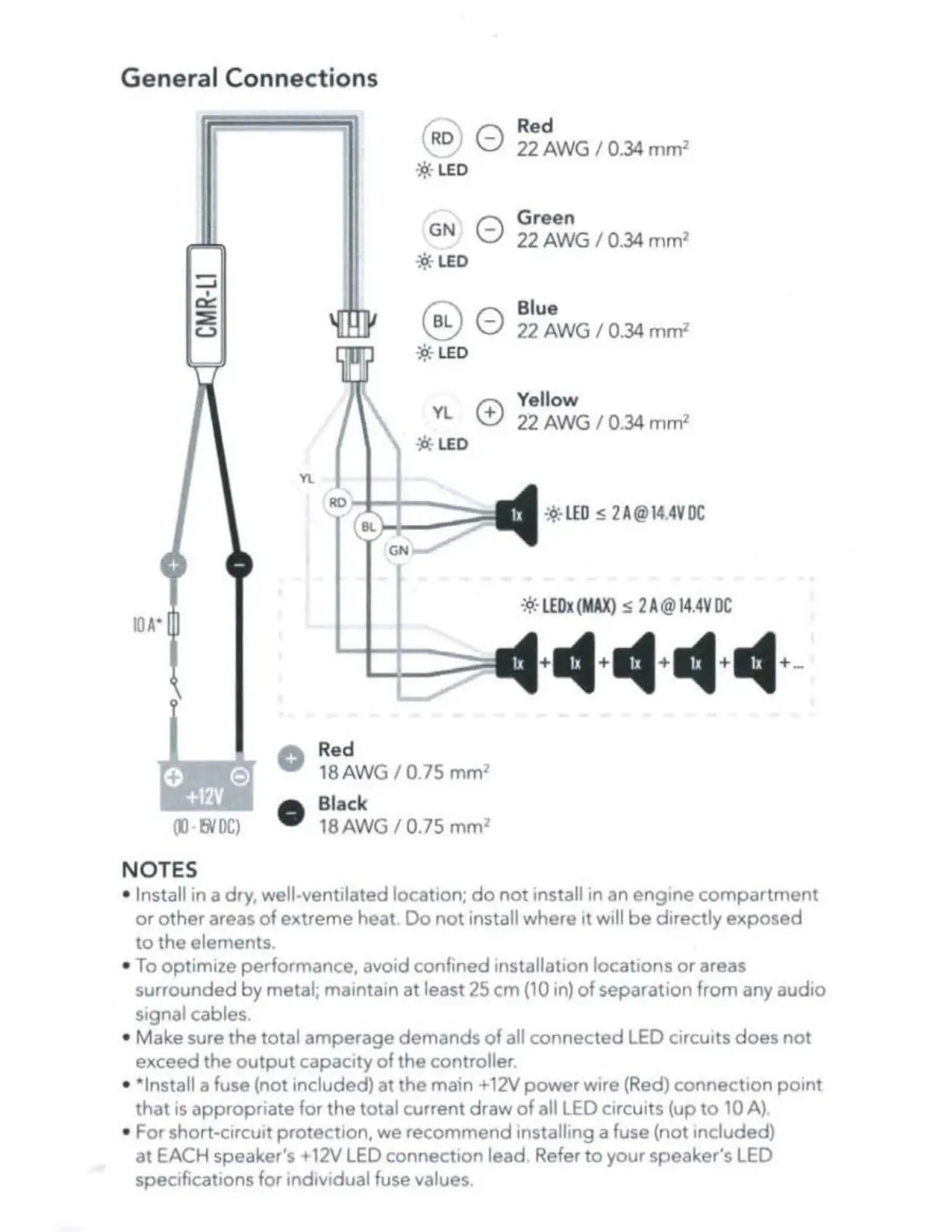
General
Connections
-
....I
I
~
~
c.;)
OO
•
fNDC)
NOTES
(
Ro
/ 0
:
iJ.
.
LED
...
GN
0
~cf;
LED
@0
:o
·-
LED
...
YL
0
~cl:
LED
Yl
RO
Red
18AW
G / 0.75
mm
2
•
Black
18
AW
G / 0.75
mm
2
Red
22
AW
G / 0.
34
mm
2
Green
22
AWG
/ 0.34
mm
2
Blue
22
AW
G / 0.34
mm
2
Yellow
22
AW
G I 0.34 mm
2
-:
9
:-
LED
s 2 A@
14
.
4V
DC
•:
«•
LEDx
(
MAX
) s 2 A@1
4.4V
DC
• Install in a dry, well-ventilated location;
do
not
install in an engine
compartment
or
ot
her
areas
of
extreme heat
Do
not
install where
it
will
be
directly
exposed
to
the elements.
• To
opt
imize performance, avoid confined installation locations
or
areas
surrounded
by
metal; maintain
at
least
25
cm (10
1n)
of
separation from any audio
signal cables.
• Make sure the
to
tal amperage demands
of
all connected LED circuits
does
not
ex
ceed
the
output
capacity
of
the controller
• *Install a fuse (not included) at the main + 12V
power
wire (Red) connection
point
that
1s
appropriate for the total current draw
of
all LED circuits (up
to
10 A)
• For short-circuit protection, we recommend installing a fuse (not included)
at
EACH speaker's +
12V
LED
connection lead Refer
to
your speaker's LED
specifications for
ind1v1dual
fuse values.
 Loading...