Do you have a question about the Clarus 500 GC and is the answer not in the manual?
Provides an overview of the manual's purpose, scope, and target audience.
Summarizes the content and purpose of each chapter within the service manual.
Explains text formatting, symbols, and icons used to convey information in the manual.
Details EMC standards for the US (FCC) and EU, and discusses RF interference susceptibility.
Illustrates and explains common safety symbols and warning labels found on the instrument.
Covers general safety practices, precautions, heated zones, environmental conditions, and hazardous chemicals.
Guides on preparing the laboratory environment and a pre-installation checklist.
Instructions for installing the autosampler unit onto the GC system.
Details on connecting gas cylinders and electrical power to the Clarus 500 GC.
Instructions for connecting various accessories, including detectors and external devices.
Information on available restrictors and their use for carrier gas control.
Procedures for autosampler maintenance, including syringe replacement and servicing.
Covers maintenance for packed, capillary, and POC injectors, including liners and septa.
Detailed maintenance procedures for ECD, FID, PID, ELCD, NPD, and FPD detectors.
Instructions for configuring HyperTerminal for firmware operations.
Steps for creating shortcuts and downloading firmware to the instrument.
Performance specifications for various column and detector configurations.
Procedure for calibrating the oven temperature using a reference thermometer.
Provides an overview of the autosampler and its main components like the tower interface.
Covers maintenance for syringes, carousel, and tower mechanisms.
Covers initial power-on diagnostics, failure recovery, and diagnostic modes.
Details diagnostic screens and modes within the chromatograph operation.
General guidance for troubleshooting common instrument issues.
Procedures for forgotten passwords and interpreting error messages.
Overview of the LEGO Interface PC Board and its sub-components.
Details electrical system components like power supply, PC boards, and controls.
Reference to schematic diagrams for the instrument's electrical systems.
Describes the mechanical components: detectors, injectors, pneumatic controls, and oven.
Details pneumatic options for optimizing column and detector performance.
Discusses the instrument's pneumatic systems and auxiliary gas controls.
Lists available service data bulletins (SDBs) for the Clarus 500 GC.
| Model | Clarus 500 GC |
|---|---|
| Category | Gas Chromatography |
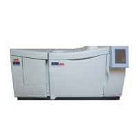
| Type | Gas Chromatograph |
| Applications | Environmental, Petrochemical, Pharmaceutical, Food and Beverage |
| Detector Options | FID (Flame Ionization Detector), TCD (Thermal Conductivity Detector), ECD (Electron Capture Detector), NPD (Nitrogen Phosphorus Detector), MS (Mass Spectrometer) |
| Carrier Gas | Helium, Hydrogen, Nitrogen |