29
ELECTRICAL CONNECTIONS
The installation should be done by a licensed electrician. All local codes must be observed.
The units come standard ready to be hard wired, using 1/2" liquid tight conduit.
The ozone generator should be wired so that the ozone generator is on when the pump is on or when water is owing
through the venturi. This can be done by using the electrical interlock box to interface with a ow switch, ORP monitor
or timer; or by using the motor control interlock (MCI) to work with a main pump.
IMPORTANT: The M-1500 & P-2000 are available in 120 volt and 240 volt models. Be sure you have the proper sys-
tem for your application. Before attempting any electrical hookup, be sure the power is OFF at the main circuit box!
To hard wire a 120V system, connect the black “hot” wire to terminal L1. Connect the white neutral wire to the L2 ter-
minal. Connect a 12 AWG jumper wire from terminals L2 to L3. Then run the green ground wire to the grounding bar.
To hard wire a 240 VAC system, connect the black wire to terminal L1 and connect the red wire to terminal L2. Con-
nect the white neutral to terminal L3. Connect the green wire to ground.
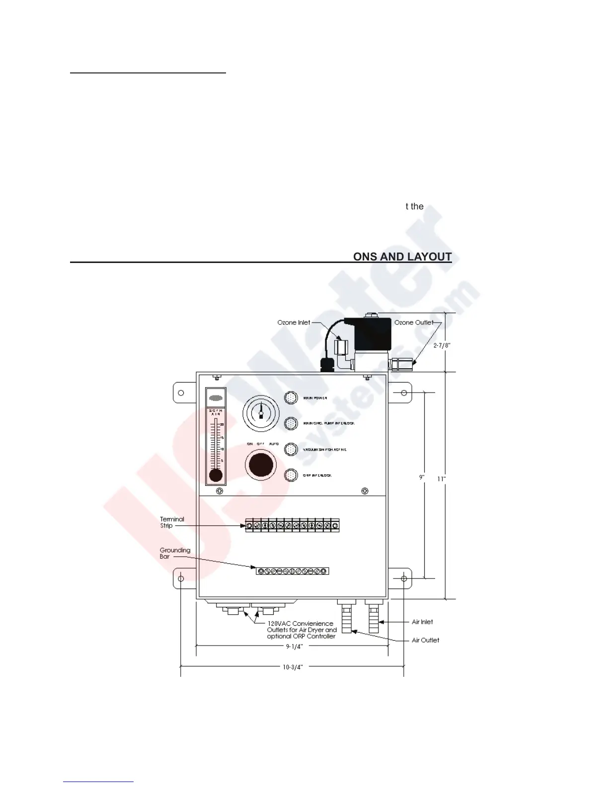
ELECTRICAL INTERLOCK BOX (OPTIONAL) DIMENSIONS AND LAYOUT
 Loading...