69
M0CZ00007-03
SYSTEM ACCESSORIES
MODULE OF RADIANT
Example to assign address 12: : Selector A = 1, selector B = 2
Serial Communication Parameters
Parameter
Mnemonic
Name
Description Value
33 Index Device address 11,12....
34 Baud Rate
Baud Rate 0=4800 1 :9600
2 :19200
1
35 Parity Parity 0=NO / 1=Odd 2=Even 0
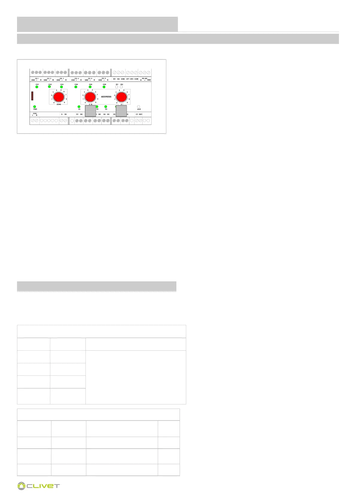
Module addressing is done using the selectors.
1 - Switch off the module
2 - Using a flat blade screwdriver, turn selectors A and B to the required position to set the address
Example to assign address 12:
Selector A = 1, selector B = 2
3 - Switch on the module
If the system configuration includes several radiant area modules (MAX 5):
the first must have address = 11
the second must have address = 12
the third must have address = 13
the fourth must have address = 14
the fifth must have address = 15
There are three red selectors on the front of the module.
To change addresses, refer to selector A and B as shown below:
SELECTOR A = Set X10
SELECTOR B = Set X1
PROCEDURE
A B
Setting parameters
Channel Parameter Value
1 P02
0 = Disabled
1 = Thermoregulation 1G
2 = Thermoregulation 2 G
3 = I/O
4 = Relay control ID
5 = Thermostat Module
2 P03
......... .....
6 P07
ONTROL4 NRG will automatically set the control of the various outputs.
Below are the parameters that are set by the autoconfiguration on the various system components; the list should be considered as indicative and is
an operational outline to be assessed based on the type and configuration of the system.
COMPONENT PARAMETERS
 Loading...