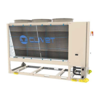
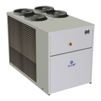
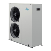
Do you have a question about the CLIVET WSAN-XEM 50.4 and is the answer not in the manual?
Provides correct unit installation, use and maintenance procedures.
Only qualified personnel can operate on the unit, as required by regulation.
Details situations causing damages to things and injuries to people.
Specifies the unit's intended application for air-conditioning.
Guidance on positioning, hydraulic, electrics, and ducting.
Plan periodic inspection and maintenance to avoid repair costs.
Unit modifications void warranty and manufacturer responsibility.
Instructions for handling unit breakdown or malfunction.
Installer must train user on operation, settings, and breakdown procedures.
Product improvements may require manual data changes.
Keep manual accessible, note unit data, and report breakdowns.
Details on serial number label and its information.
Identifies each unit uniquely and is used for spare parts orders.
Note serial number data for easy access when assistance is needed.
Observe external packaging instructions for storage.
Instructions for verifying weight, identifying critical points, and lifting.
Instructions for safe removal of packaging material.
Details on the optional anti-vibration mount support.
Ensures good unit operation, maintenance access, and safety.
Criteria for external installation, limiting vibration, and avoiding obstacles.
Procedure for managing condensate water to avoid wetting pedestrian areas.
Installer responsibility for safety valve installation per EN 378.
Specifications for water quality, including limits and potential issues.
Measures to prevent freezing of water connections.
Considerations for using anti-freeze solutions, including pressure drop.
Requirements for water flow-rate within exchanger limits and system conditions.
Ensuring sufficient water content to avoid frequent compressor cycling.
Steps for connecting hydraulic lines, including precautions.
Defines components and positioning for recommended hydraulic connections.
Details on water filter installation and maintenance.
Ensures unit shutdown if water is not circulating, requiring specific installation.
Steps for filling, venting, and testing the hydraulic system.
Details on hydronic assembly configuration options.
Details on the optional domestic hot water valve.
Configuration for producing hot water during cooling mode.
Information on unit electrical data from the serial number label.
Steps for making electrical connections, ensuring safety and compliance.
Guidelines for laying signal and data cables to avoid interference.
Table specifying cable sections and tightening torques for power input.
Diagram and list of customer-performed electrical connections.
Instructions for connecting to the unit via computer for configuration.
Requirements for Modbus/LonWorks/BACnet cable connections.
Specifications for LonWorks cable type and configurations.
Details for connecting to the unit via BACnet IP.
Information on distance and connection for remote control options.
Operations for unit start-up by qualified technicians.
List of checks before unit power supply and start-up.
Detailed sequence for unit start-up after power supply.
Checks for the refrigeration circuit, including pressure and oil stains.
Checks for the water circuit, including cleaning, filling, and air evacuation.
Checks for the electric circuit, conductors, voltage, and phase balance.
Instructions for connecting and checking compressor crankcase heaters.
Checks for air/water temperatures, voltage, and electrical load absorptions.
Check connections of remote controls and optional components.
How to limit absorbed electric power using an external 0-10 Vcc signal.
Configuration of temperature curves for setpoint adjustment.
Correction of setpoint based on water reset parameters.
Details on ECOSHARE function for managing multiple units.
Checks on evaporator water flow-rate and pressure drops.
Identifying operating data for unit control over time.
Considerations for reduced load operation and potential damages.
Information on directive for installers, users, and maintenance technicians.
Information on LED indicators for status and alarms.
Explanation of display variables and their meanings.
Description of control panel keys and their functions.
Procedure for changing the unit's operating state (OFF, ECO, ON).
Procedure for changing the unit's operating mode (Cooling, Heating).
Steps to modify setpoint values for cooling, heating, and hot water.
How to set events (Off, Eco, On) for each day of the week.
Procedure to display machine state and general circuit information.
Settings for the control panel keyboard and its functions.
Procedure for identifying, resetting, and managing alarms.
Maintenance must be done by authorized centres or qualified personnel.
Schedule for performing inspections every 6 months minimum.
Advisable to create a unit booklet for noting interventions.
Procedures for turning off the unit during long periods of inactivity.
Instructions for cleaning the air coil and preventing fin damage.
Checks for fan fixing, bearings, and terminal protection covers.
Importance of clean exchanger surfaces for thermal exchange.
Checks for leaks, bearing status, and terminal protection of pumps.
Check that no impurities prevent correct water passage.
Checks for flow switch operations and removal of incrustations.
Instructions regarding the compressor supply line shut-off valve seal.
Checks for closure and operation of the crankcase heater.
Information on advanced scroll temperature protection.
Check the condition of insulations and renew seals if necessary.
Steps for system discharge, including evacuation and cleaning.
Water diagram for VARYFLOW+ system with two inverter pumps.
Water diagram for hydronic assembly with one ON/OFF pump.
Water diagram for hydronic assembly with two ON/OFF pumps.
Details on anti-vibration mount support codes and dimensions.
Procedures for disconnecting the unit, recovering gas and solutions.
Unit must be sent to authorized centres for dismantling and disposal.
Information on waste electrical and electronic equipment disposal regulations.
Common risk situations not controlled by the manufacturer.
Risks associated with handling operations without proper precautions.
Risks from incorrect installation: leaks, electric shock, damage.
Risks from anomalies, accidental contact, non-qualified maintenance.
Risks from refrigerant exposure, safety valve activation, and heat sources.
Risks from defects in tubing or attachments causing leaks or projection.
Dimensional drawings and specifications for specific unit sizes.
Dimensional drawings and specifications for specific unit sizes.
Dimensional drawings and specifications for specific unit sizes.


