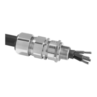
INSTALLATION INSTRUCTIONS FOR CMP CABLE GLAND TYPES “E”
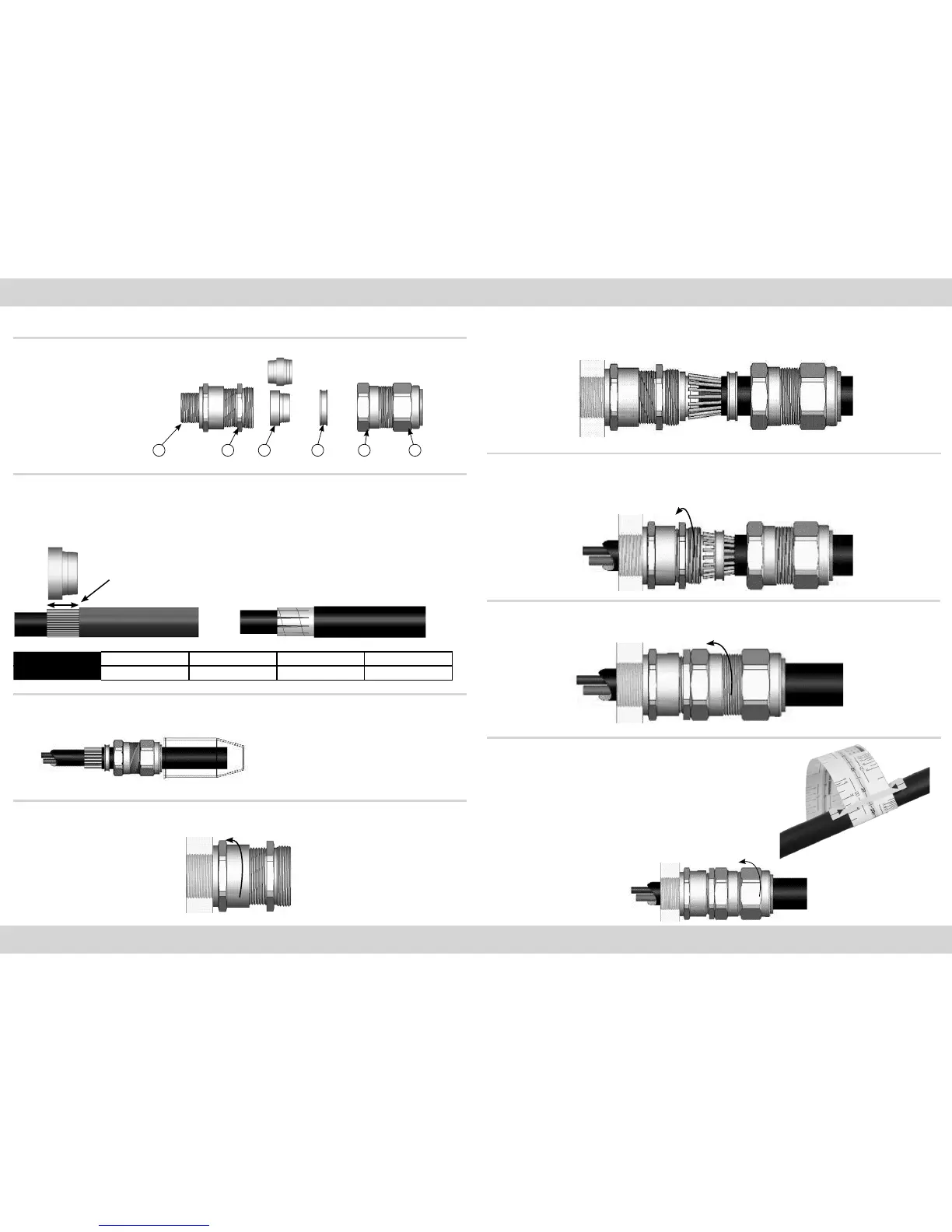
CABLE GLAND COMPONENTS - It is not necessary to dismantled the cable gland any further than illustrated below
1. Entry Component
2. Main Item
3. Detachable Armour Cone
4. AnyWay Clamping Ring
5. Body
6. Outer Seal Nut
PLEASE READ ALL INSTRUCTIONS CAREFULLY BEFORE BEGINNING THE INSTALLATION
1. If required fit shroud over the cable outer sheath;
Prepare the cable by stripping back the cable outer sheath and armour to suit the equipment geometry.
Expose the armour by stripping back the outer sheath further using the table below as a guide.
If applicable remove any tapes or wrappings to expose cable inner sheath.
Cable Strip
Length “L”
Tape armour should be further
prepared by cutting the tape into
strips as shown below:
CABLE GLAND SIZE 20S/16, 20S, 20 25S, 25, 32, 40 50S, 50, 63S, 63 75S, 75, 90, 100, 115, 130
CABLE STRIP LENGTH “L” 12mm 15mm 18mm 20mm
2. Separate the gland into two sub-assemblies “A & B”. Ensuring that the Outer Seal Nut (6) is relaxed, pass sub-assembly “B” over
the cable outer sheath and armour followed by the “AnyWay” clamping ring (4).
Note: On maximum size cables the clamping ring may
only pass over the armour.
3. Ensure that the inner seal is relaxed by slackening the Main Item (2). Secure sub-assembly “A” into the equipment either by
screwing the Entry Item (1) into a threaded hole or by securing it in a clearance hole using a locknut as applicable.
4. Locate the Armour Cone (3) into its recess in the Main Item (2). (For E1FU and E2FU variants, make sure the correct side of
the cone is outermost - grooved for braid/tape armour and stepped for SWA). Pass the cable through sub-assembly “A” until the
armour engaged with the cone. Spread the armour evenly around the cone.
5. While continuing to push the cable forward to maintain contact between the armour and the cone, tighten the Main Item (2)
until the inner seal makes contact with the cable inner sheath (heavier resistance is felt at this point). Tighten a further full turn.
NOTE: The earthing device on E2* type glands will automatically engage the lead sheath.
6. Hold the Main Item (2) with a spanner and tighten sub-assembly “B” onto sub-assembly “A” using a spanner until all available
threads are used.
7. Only using finger pressure, tighten the outer seal nut assembly (6) until light resist-
ance to tightening is met.
Then either use the outer seal tightening guide tape or table on the rear of the page to
determine how much further to tighten the seal using a spanner (using the outer seal
tightening guide is recomended).
Wrap the outer seal tightening guide tape around the cable to show the amount of
spanner turns needed (as shown here). Make sure the correct side of the outer seal
tightening guide tape is used depending on the cable gland size.
1. 2. 3. 4. 5. 6.
Universal Cone
(E1FU, E2FU) use
stepped side for SWA
and grooved side for
all other armours
SUB ASSEMBLY A SUB ASSEMBLY B
 Loading...