Do you have a question about the CO-TRUST E10 Series and is the answer not in the manual?
General instruction to follow safety guidelines.
Explanation of DANGER and CAUTION symbols and their implications.
Specific safety measures for handling electrical wiring and connections.
Safety guidelines for handling the driver, including avoiding vibration and wet conditions.
Avoiding hazardous environments like dust, corrosive gases, and flammable materials.
Precautions regarding ventilation, installation method, and handling errors.
Detailed technical specifications of the E10 Series AC Servo Driver.
Details on speed rate of change, position output, digital input/output, and analog input.
Analog input ranges, communication control methods, and environment parameters.
Breakdown of E10 Series Servo Driver model naming conventions.
Breakdown of Servo Motor model naming conventions.
Breakdown of cable model naming conventions.
Detailed technical parameters for various E10 servo motor types.
General guidance for installing the servo driver and motor.
Requirements for the installation environment to ensure proper operation.
Specifies operating temperature, humidity, altitude, and vibration limits.
Describes the base plate installation method and orientation.
Guidelines on mounting orientation and spacing for ventilation.
Environmental requirements for installing the servo motor.
Important considerations and installation steps for the motor.
Overview of the servo driver's external port schematic diagram.
Details on the X5 terminal for main power input and related specifications.
Details on the X4 terminal for control power input and its requirements.
Description of DCN, RB1, and RB2 terminals for braking.
Further details on DCP, DCN, and bus terminals, including cautions.
Details of the X6 terminal for motor power cable connections.
Wiring diagrams for the motor's permanent magnet safe brake.
Wiring table and diagram for the X2 encoder input terminal.
Pin sequence schematic for the X1 control signal terminal.
Visual representation of wiring for external position control.
Visual representation of wiring for external speed/torque control.
Details on RJ45 communication interface, terminal resistance, and factory reset.
Table showing communication rates and maximum distances for network cables.
PC connection via USB/RS485 and setting terminal resistance.
Method for terminating CANopen networks to improve reliability.
Overview of signals, commands, and their functions.
Explains how to select the source for position, speed, and torque commands.
Details on CCW/CW pulse forms and A/B phase relationships.
Defines control signals and choices for DI/DO configuration.
Explains parameter P73 for selecting control command source and pin distribution.
Standard and parameter-defined function assignments for digital input pins.
Detailed mapping of parameters, bits, pins, symbols, and function codes.
How to set logic levels for external DI and enabling shutdown methods.
How P72 selects logic levels for CCW/CW overtravel, zero-speed clamp, and original switch.
How P79 determines functions for DOUT1-DOUT4.
Parameter P79 mapping for digital output functions in different control modes.
Steps to allocate pin functions and use the simulation IO feature.
Screenshot and explanation of the "Pin function configuration & simu IO" interface.
Advice on configuring pins and using simulation functions.
Explanation of control signals like Control Signal Power and Servo-ON.
Details on overtravel inhibit signals and their parameter settings.
Function of the DIV signal for selecting electronic gear ratio numerators.
Function of GAIN and TL-SEL signals for switching gains and torque limits.
Function of INH and ORG_SW signals for pulse inhibition and homing.
Function of C-MODE and CL signals for mode switching and deviation clearing.
Function of Homing and ZeroSPD signals.
Function of PosLock and Pos_Start signals.
Function of SPD_dir and A-CLR signals.
Details on S-RDY, ALM, and TLC output signals.
Function of POS-OK, SPD-OK, and BK signals.
Function of ZSP and INTSPD signals.
Details on PULS+/-, DIR+/- inputs and AGND.
Details on A+, B+, Z+ outputs and GND.
A comprehensive list of servo driver parameters with their addresses.
Continuation of the parameter list, covering addresses 71-134.
Continuation of the parameter list, covering addresses 136-234.
Explains parameter meanings and provides adjustment advice.
Configuration of the communication address for serial port communication.
Selection of various control modes for the servo driver.
Setting torque limitation signals in clockwise and counterclockwise directions.
Configuration to enable or disable overtravel inhibit signals.
Selecting command sources for external speed and communication control modes.
Selecting communication given command sources for position, speed, and torque.
Selection of external zero-speed clamp signal functions.
Selecting output signals for torque limitation control.
Selecting output signals for zero-speed limit control.
Setting the communication speed for RS485.
Setting the communication rate for CANopen.
Setting communication timeout to detect abnormal communication.
Configuring the servo-on state upon power-on.
Setting gain and integration time for the current control loop.
Setting the gains for the first position and velocity control loops.
Setting integration time for velocity control loops.
Setting filter types for velocity detection.
Setting time constants for torque command filters.
Setting feedforward value for position control mode.
Setting filter time for velocity feedforward.
Setting the gains for the second position and velocity control loops.
Setting the ratio of load inertia to rotor inertia.
PDO inhibit time and CANopen alarm configuration.
DI filter time selection and interpolation command setting.
Setting logic for inverting B-phase pulse output.
Setting command pulse ratio from external feedback pulses.
Setting software filter time for command pulses.
Selecting from various homing modes for servo operation.
Selecting conditions for switching between 1st and 2nd gains.
Setting delay time for switching between gains.
Setting the speed for JOG (test run) operation.
Selecting absolute/relative position for multi-position control.
Selecting external DI logic levels for various functions.
Selecting pin allocation and control command source.
Configuration of digital input multiplexing functions for pins.
Configuration of digital output multiplexing functions.
Setting command pulse direction and input method.
Setting to disable command pulse inhibit function.
Setting command pulse ratio parameters.
Setting primary delay filter for pulse command to improve smoothness.
Selecting motor rotation direction in communication mode.
Setting the method for clearing the deviation counter.
Setting the relationship between motor speed and input analog voltage.
Setting the logic level for analog speed command.
Adjusting zero-drift for analog speed and torque commands.
Setting 1st to 8th internal speeds for command.
Setting the primary delay filter for analog speed/torque commands.
Setting acceleration/deceleration times for speed control modes.
Limiting speed based on external pulse or parameter P98.
Setting the relationship between motor torque and input analog voltage.
Setting the logic level for analog torque command.
Setting restriction values for torque limits.
Setting the range for the positioning complete signal.
Setting the threshold for zero-speed detection.
Setting the threshold value for the arrival speed signal.
Setting output conditions for the positioning complete signal.
Setting driving conditions during over-travel inhibition.
Setting position increment during homing based on original switch.
Setting delay times for mechanical brake release.
Configuring brake resistance and overload protection.
Setting torque limitation during emergency stop or overtravel.
Setting the detection range for excessive position deviation.
Setting the excess voltage level for analog commands.
Setting the over-load level for the motor.
Setting the over-speed level for the motor.
Displaying recent alarm records of the servo.
Information on software version and manufacturer-specific parameters.
Displaying the current system state of the servo.
Displaying the present control mode of the servo.
Displaying the current alarm state of the servo.
Displaying the control signal command status of the servo.
Indicating system status outputs like Servo-Ready, Alarm, etc.
Reporting states of external interface signal inputs/outputs.
Setting input and output values for external analog signals.
Total command/feedback pulses, coordinates, and pulse deviation.
Present command/actual speed, velocity deviation, torque, and deviation.
Busbar voltage and current alarm status.
Torque output, discharge resistance, and overload loading rates.
Reserved parameter for motor identification.
Explains reasons for 'No-Motor Running' status.
Displays EtherCAT communication status.
Register for setting pulse number in special speed-position mode.
Controls EtherCAT communication, including enabling servo and clearing alarms.
Codes for various communication control functions.
Extended control signals for communication mode.
Controls servo enabling, alarm clearing, and relative position command cancellation.
Setting pulse number as filters for signal detection.
Setting alarm number for pulse detection issues.
Setting given positions for communication position control.
Setting given speeds for communication speed control.
Setting given torques for communication torque control.
Overview of Modbus and CANopen communication protocols.
Explanation of CANopen communication features and messages.
Standard properties of the E10 series in CANopen protocol.
Explanation of the Object Dictionary for CANopen devices.
Illustrates connecting E10 servo with CPU226M-CAN.
Refers to an application example for CANopen config.
How to diagnose CANopen network issues via indicators or status bytes.
How to interpret the E10 CANopen indicator.
Using MagicWorks PLC status bytes for CAN station diagnosis.
Explanation of the built-in Modbus RTU protocol and its commands.
Significations of Modbus function codes and parameter mapping.
Request and response frame format for reading parameters.
Format of the response frame after a successful read operation.
Request and response frame format for writing a single parameter.
Request and response frame format for writing multiple parameters.
Request frame for slave abnormal response and error code descriptions.
Detailed descriptions of Modbus error codes.
Overview of applying communication and external control modes.
Steps and guidance for using the MagicWorks Tuner software.
Step-by-step guide to starting and configuring MagicWorks Tuner.
Introduction to test run procedures in communication control modes.
Steps for wiring, mode selection, and enabling the servo.
Procedures for test runs in communication position, speed, and torque modes.
Procedure for test run in communication torque mode.
Overview of External Position, Speed, and Torque control modes.
How to achieve position control using external pulses.
How to achieve speed control using analog voltage or DI signals.
How to achieve torque control using external analog voltage.
Example operations and relevant parameters for external position control.
Wiring diagrams for PLC connection (NPN and PNP output).
Relevant parameters for external speed control mode.
Relevant parameters for external torque control mode.
Overview of Communication Position, Speed, and Torque control modes.
Relevant parameters for communication position control mode.
Step-by-step guide for CANopen communication in position control mode.
Configuring digital input multiplexing for CANopen communication.
Setting logic levels for sensor signals in CANopen.
Steps to configure CANopen communication using MagicWorks PLC.
Adding the E10 servo as a slave in the CAN bus configuration.
Choosing parameters for communication position control of the E10 Servo.
Writing values to parameters for communication mode operations.
How to confirm the servo is ready using output state parameter.
Illustrative network diagrams for PLC programs.
Visual representations of network logic for servo operations.
Relevant parameters for communication speed control mode.
Steps for master initialization in Modbus communication.
Writing parameters sequentially to the driver via Modbus.
Illustrates Modbus frames for parameter writes.
More examples of Modbus frames for parameter writes.
More examples of Modbus frames for parameter writes.
Procedure for reading parameters R200-R229 via Modbus.
Relevant parameters for communication torque control mode.
Parameters for torque control functions.
Overview of the homing function for finding the origin point.
Key parameters affecting homing function behavior.
Detailed descriptions of 16 different homing modes.
Explanation and diagram for Homing Mode 1.
Explanation and diagram for Homing Mode 2.
Explanation for Homing Mode 3.
Explanation and diagram for Homing Mode 4.
Explanation and diagram for Homing Mode 5.
Explanation and diagram for Homing Mode 6.
Explanation and diagram for Homing Mode 7.
Explanation and diagram for Homing Mode 8.
Explanation and diagram for Homing Mode 9.
Explanation and diagram for Homing Mode 10.
Explanation and diagram for Homing Mode 11.
Explanation and diagram for Homing Mode 12.
Explanation and diagram for Homing Mode 13.
Explanation and diagram for Homing Mode 14.
Explanation and diagram for Homing Mode 15.
Explanation and diagram for Homing Mode 16.
Examples of applying homing function in different control modes.
Step-by-step guide for homing in communication position mode.
Ensuring overtravel inhibit function is effective for homing.
Setting logic levels for input signals used in homing.
Setting coming back and creep speeds for homing.
Enabling the servo and homing command for the function.
Checking homing effectiveness, completion, and outputting signal.
Step-by-step guide for homing in external position control mode.
Steps for homing configuration, enabling servo, and writing/reading servo data.
Multi-control using communication mode for position, speed, and torque.
Key parameters for multi-control functions.
Step-by-step guide for communication multi-position control.
Advice and notes on using the multi-control function.
Explanation of pulse adjustment via communication command.
Key parameters for pulse adjustment function.
Step-by-step guide for pulse adjustment.
Mode switching between position and speed modes.
Parameters related to special speed-position control mode.
Explanations for parameter values related to mode switching.
Detailed explanations and diagrams for switching scenarios.
Detailed explanations and diagrams for switching scenarios.
Detailed explanation and diagram for switching scenario.
Setting external sensor input pins for special control modes.
Illustrates operations in special speed position mode.
Steps for selecting mode, detecting signals, and setting parameters.
Overview of alarm indicators and fault recognition.
Details on alarm codes, types, and failure descriptions.
More alarm codes, types, and failure descriptions with solutions.
Final alarm codes, types, and failure descriptions with solutions.
Important notes regarding alarm clearing, storage, and servo behavior.
General guidance on adjusting servo gain parameters.
Block diagram illustrating the servo system control structure.
How to set gain parameters for current and speed loops.
Explanation of speed loop gain and its effect on rigidity and oscillation.
Graphical examples of speed loop curves at different gain settings.
Adjusting speed loop integration for faster response and stability.
Setting position loop gain for rigidity and response, potential for oscillation.
Graphical examples of position loop curves at different gain settings.
Selecting filter type for speed detection to improve noise restraint.
Using torque filter time constant to restrain vibration.
Using speed feedforward to shorten response time in position control.
Setting filter time to restrain noise in speed feedforward.
Setting load inertia ratio to improve system gain, caution on oscillation.
Graphical example of speed loop curve with insufficient integration time.
Using curve graphics for servo performance adjustment.
Using the MagicWorks Tuner interface to check loop curves.
Units for given commands in current, speed, and position loops.
Principles for servo gain adjustment and interdependent parameters.
Precautions and safety measures before performing gain adjustment.
Steps for adjusting gain parameters with MagicWorks Tuner.
Switching between two sets of gain parameters for optimal performance.
Parameters related to delay time for gain switching.
Parameters P20-P31 related to gain switching.
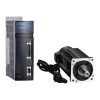
| Brand | CO-TRUST |
|---|---|
| Model | E10 Series |
| Category | Servo Drives |
| Language | English |