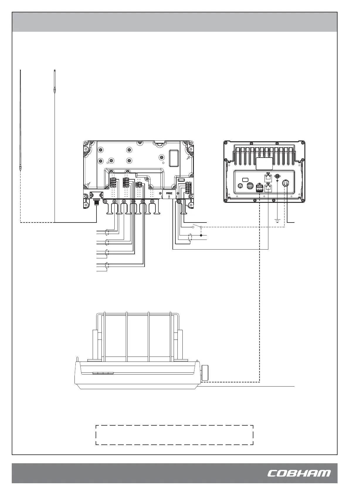
System Confi guration - Example
98-137263-A
www.cobham.com/satcom
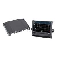
SAILOR 6004 Control Panel
ACC
AUX
TEST
PWR
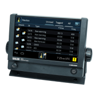
SAILOR 6390 Navtex Receiver
NMEA IN (from eg. GPS)
NMEA IN (from INS)
NMEA OUT (to INS)
ALARM RELAY (normally closed)
+
-
+
-
+
-
Active Navtex Antenna
12 VDC @ 60 mA max.
Passive
Antenna
12-24 VDC
SAILOR H1252B Printer
VBAT+
VBAT-
PE
Shield
ON IN
ON OUT
12-24 VDC
32 VDC @ 500 mA max.
GND at talker end
GND at talker end
12-24 VDC
(internal fuse 1 A)
(internal fuse 3.15 A)
The device requires ON IN to be connected to VBAT- in order to power up.
This can be done by a dedicated switch, permanent wiring or connection
to a Cobham device supporting ON OUT (e.g. SAILOR 6004 Control Panel).
For further information about installation, download the
installation manual from www.cobham.com/satcom
 Loading...