Do you have a question about the Cobra MT-500 and is the answer not in the manual?
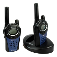
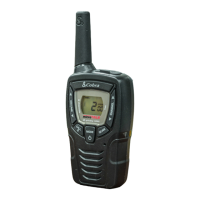
General technical specifications for the MT-500 2-way radio.
Parameters and conditions for testing the radio's performance.
Detailed specifications and test results for the receiver section.
Instructions for inserting batteries into the MT-500.
Procedure for powering the MT-500 on and off.
Explanation of the automatic battery saving feature.
How to choose and change the radio channel.
Information on the battery status indicator.
Procedure for initiating a call to another radio.
Procedure for transmitting a message to another radio.
Audible tone indicating end of transmission.
How to listen for incoming transmissions.
Function to reduce unwanted noise.
Feature to temporarily extend communication range.
Overview of the radio's circuit design and function.
Detailed explanation of the receiver's internal workings.
Description of the radio frequency input stage.
Explanation of the first mixing stage in the receiver.
Details on the intermediate frequency filtering and amplification.
Function of the second mixer, IF, and FM detector.
Explanation of the audio output amplification circuit.
Explanation of the radio's transmission circuit and components.
Description of the audio pre-emphasis circuit.
Details on the frequency synthesis system.
Function of the receive/transmit buffer amplifier.
Explanation of the Phase Locked Loop synthesizer.
Role of the CPU and memory in radio operation.
Diagnosing and resolving issues when the unit is completely non-functional.
Troubleshooting no audio output from the speaker.
Addressing issues with lack of speaker noise.
Diagnosing problems with audio modulation.
Resolving issues with the LCD screen.
Troubleshooting the LCD backlight.
Steps for setting up test equipment for alignment.
Procedure to adjust RX VCO voltage.
Procedure to adjust TX VCO voltage.
Procedure for frequency adjustment.
List of necessary test equipment for transmitter alignment.
Procedure for adjusting AF modulation.
List of necessary test equipment for receiver alignment.
Procedure for adjusting receiver squelch.
Procedure for adjusting receiver distortion.
Detailed steps for aligning the transmitter section.
Detailed steps for aligning the receiver section.
Table listing channel frequencies for the MT-500.
Lead identification and internal connections for ICs.
Lead identification and internal connections for transistors.
Lead identification for diodes.
Voltage readings for integrated circuits.
Voltage readings for IC100.
Transistor parameters for the receiver section.
Transistor parameters for the transmitter section.
Further transistor parameters.
Visual representation of parts with corresponding list.
Continuation of the exploded view part listing.
Further details of the exploded view part list.
Detailed list of components with part numbers.
Continued list of components and their part numbers.
More details on components and part numbers.
Final entries in the component list.
| Battery Life | Up to 10 hours |
|---|---|
| Weather Alert | Yes |
| VOX | Yes |
| Waterproof | No |
| Channels | 22 Channels |