Installing In-Sight
®
1720 Series Wafer Readers
15
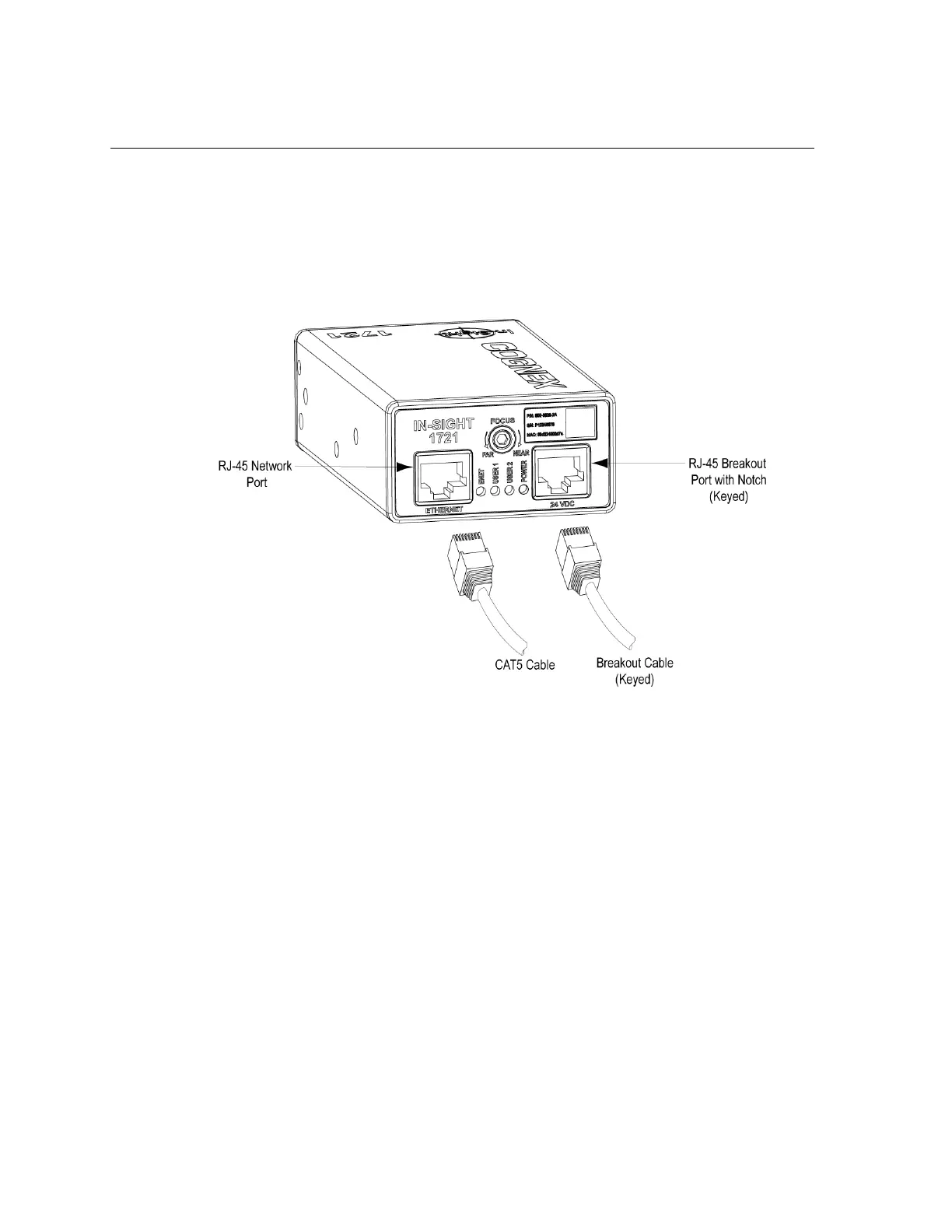
3.4 Connect the Network and Breakout Cables
The wafer reader has two RJ-45 connector ports: the Network Port and the Breakout Port
(see Figure 3-4). The Network Port provides the Ethernet connection for network
communications. The Breakout Port supplies connections for the 24VDC power source, I/O,
acquisition trigger, and serial communications.
Figure 3-4: Location of RJ-45 Ports
3.4.1 Connect the Network Cable
• If you are connecting to an Ethernet switch/router, plug one of the RJ-45
connectors of a CAT5 straight-pinned cable or crossover cable into the Network Port
(labeled Ethernet) and plug the other end into an available port on the switch/router.
• If you are connecting directly to a wafer reader from a remote host, plug one
end of a CAT5 network cable or crossover cable into the wafer reader’s Network Port
(labeled Ethernet); plug the other end into the remote host’s Ethernet port.
3.4.2 Connect the Breakout Cable
The breakout cable provides access to the wafer reader’s power, serial communications, and
I/O lines. The RJ-45 connector on this cable is “keyed” to the notch in the Breakout Port, and
cannot be inadvertently plugged in to the Network Port. See Section 5.2.2: Breakout Port Pin
Assignments on page 33 for the Breakout Cable’s wiring details.
To connect the wafer reader using the optional 1350 Breakout Module, refer to Appendix B.
 Loading...