Do you have a question about the Coinco MAG50B and is the answer not in the manual?
Provides information on installing, operating, and maintaining Coinco's MAG Series bill acceptors.
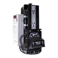
Lists and describes available MAG Series bill acceptor models and their interfaces.
Instructs users to record serial numbers for service and warranty purposes.
Guides on inspecting the unit for shipping damage and retaining packing materials.
Explains the function of the main logic board and its components.
Details power requirements, operating temperature, humidity, weight, and physical dimensions.
Provides detailed diagrams and measurements for MAGxxB and MAGxxSA models.
Explains how to customize the unit using option switches for specific account requirements.
Step-by-step guide for setting the option switches using the access hole.
Provides a numbered procedure for installing the bill acceptor into a vending machine.
Describes how the bill acceptor detects the insertion of a bill using sensors.
Explains the process of determining bill authenticity using optical and magnetic sensors.
Details how authentic bills are stacked and credit is issued.
Explains the process for rejecting invalid bills and returning them to the customer.
Explains the function of various internal components like sensors and motors.
Sensors ensuring correct bill width and feed alignment.
Sensor confirming bill readiness for transport after alignment.
Sensors performing optical checks for bill validation.
Sensor checking magnetic properties for bill validation.
Lever monitored to detect bill stacking or tampering attempts.
Sensor indicating the position of the stacker pusher plate.
Sensor determining transport motor speed and bill position.
Illustrates the wiring and connections for MAG50B/MAG52B models.
Illustrates the wiring and connections for MAG50SA/MAG52SA models.
Provides instructions for disassembling the MAG bill acceptor.
Step-by-step guide for removing the bill box from the unit.
Details how to remove the main logic board from the logic box and frame.
Instructions on how to detach the lower housing from the main frame.
Procedure for removing the intermediate frame using a screwdriver.
Steps to remove the inlet mask using a Phillips screwdriver.
How to detach the mounting frame and grounding spring.
Procedure for separating the chassis from the main frame.
Instructions for disassembling the chassis assembly.
How to remove the pusher plate from the stacker gear box assembly.
Steps to remove the encoder sensor and stacker board.
Guide to removing chassis belts and pulleys.
Steps to detach the transport and stacker motor assemblies.
How to remove the upper sensor board from the chassis.
Instructions for removing the anti-pullback lever and spring from the chassis.
Instructions for disassembling the lower housing.
Steps to remove the transformer from the lower housing.
How to detach the lower sensor board.
Steps to remove the magnetic roller and its spring.
Guide to removing the lower housing anti-pullback lever and spring.
Instructions for removing lower housing rollers and pulleys.
Detailed procedure for cleaning the MAG50 bill acceptor.
Specific cleaning procedure for units affected by salt water.
Introduces the troubleshooting guide and general checks.
Explains how to interpret diagnostic codes indicated by LED flashes.
Diagnoses issues based on LED blink patterns starting with no or few blinks.
Continues diagnosis for LED blink patterns from 4 to 7 blinks.
Continues diagnosis for LED blink patterns from 8 to 11 blinks.
Continues diagnosis for LED blink patterns from 12 to 15 blinks.
Continues diagnosis for LED blink patterns from 16 to 18 blinks.
Exploded view and parts list for the main frame of MAG50B/MAG52B/MAG52BX.
Exploded view and parts list for the main frame of MAG50SA/MAG52SA.
Exploded view and parts list for the lower housing assembly.
Exploded view diagram of the chassis assembly.
Detailed parts list for the chassis assembly.
Exploded view and parts list for the logic board and case assembly.
Exploded view and parts list for the intermediate frame assembly.
Exploded view and parts list for the cashbox assembly.
Lists and illustrates different types of harnesses for various models.
Lists various interface harnesses and their connectivity details.
| Brand | Coinco |
|---|---|
| Model | MAG50B |
| Category | Bank Note Validator |
| Language | English |