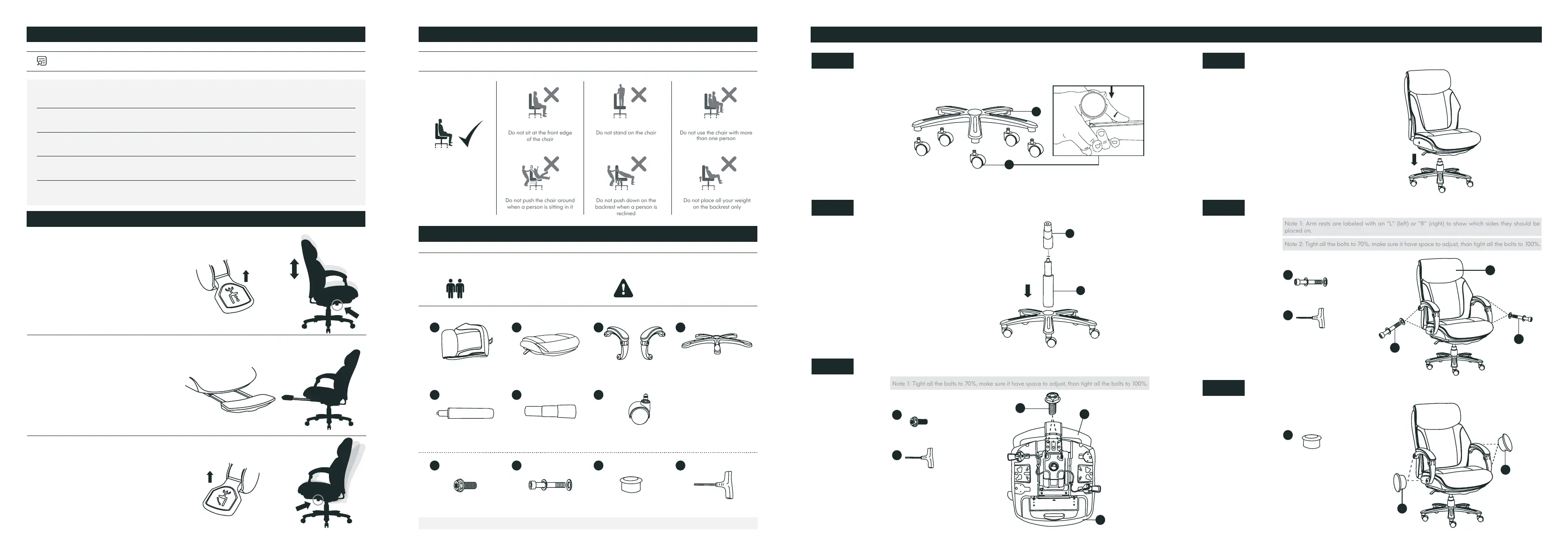
Note 1: Arm rests are labeled with an "L" (left) or "R" (right) to show which sides they should be
placed on.
Note 2: Tight all the bolts to 70%, make sure it have space to adjust, than tight all the bolts to 100%.
Back Cushion *1
Bolts M8*16mm *4
Lift *1
Seat Cushion *1
Bolts M8*57mm *4
Lift Cover *1
Arms *2
Plastic Caps *4
Casters *5
Star Base *1
Bolts M8*16mm *4
Plastic Caps *4
Bolts M8*57mm *4
Wrench *1
Wrench *1
Wrench *1
1
1
9
10
10
9
1
11
8
5
6
5
2
2
9
6
3
10
7
4
8
10
9
11
11
11
Pneumatic Seat Height
Adjustment
Tilt Angle Adjustment
Convenient Hidden Footrest
Pulling the lever upwards enables
height adjustment of the seat, then
the seat can be locked at a xed
height by releasing the lever.
Simply pull up the lever and recline
back to adjust the tilt angle, and then
push down to lock the backrest.
Simply pull out the footrest by
hand and kick it back by your feet
to retract
PRODUCT FEATURES
ASSEMBLY PARTS AND TOOL
ASSEMBLY INSTRUCTIONS
WARNING SAFETY INFORMATION
WEIGHT CAPACITY FOR SEATING: 400LBS
Sit in the center of the
chair with your back
against the backrest
Do not push the chair around
when a person is sitting in it
Do not sit at the front edge
of the chair
Do not push down on the
backrest when a person is
reclined
Do not stand on the chair
Do not place all your weight
on the backrest only
Do not use the chair with more
than one person
BEFORE YOU GET STARTED, A FEW POINTERS:
PLEASE MAKE SURE ALL THE PARTS ARE INCLUDED. MISSING PARTS?
support@colamyhome.com
Mind the important safety
information
Having a friend to help makes
assembly extra-easy
Turn the Star Base(4) upside down, then press the Casters(7) into the holes at the end of
each base leg.
Push the seat cushion down onto the lift rmly until the connection is secure.
Insert the Lift(5) into the center hole of the Star Base, the Lift Cover(6) should be placed
over the Lift.
Attach the Arms(3) to the Seat Cushion(2) and Back Cushion(1) with FOUR M8*57mm
Bolts(9), using the Wrench(11).
Attach the Back Cushion(1) and Seat Cushion(2) with FOUR M8*16mm Bolts(8), tighten all
the bolts with the Wrench(11).
Press the Plastic Caps(10) into the Arms holes to cover the bolts.
Step 1 Step 4
Step 2 Step 5
Step 3
Step 6
7
4
Note 1: Tight all the bolts to 70%, make sure it have space to adjust, than tight all the bolts to 100%.
Please read the instructions carefully and follow the assembly steps.
To ensure proper assembly, please follow all steps and use all parts provided. Not following
this warning may result in serious injury to you or others.
To prevent misalignments, keep the screws loose and do not tighten them until they are all
in their correct positions.
Avoid overtightening or forcing the screws, as this could cause them to break, strip, or
damage the threads of the holes.
Using the wrong size of screws for a particular part could cause damage to the screw or the
part.
Please lubricate all moving parts regularly and tighten all bolts and screws every 6 months,
or as needed.
 Loading...