STANDARD WHEEL ADJUSTMENT & REMOVAL
To Remove Rear Wheel
Move the chain onto the smallest rear sprocket. Disengage the brake quick release lever
if your bicycle is so equipped. Loosen both axle nuts by turning in a counter clockwise
direction. Pull the derailleur mechanism gear for additional clearance. Remove the rear
wheel by sliding forward and out of the frame.
To install wheel, locate the top section of the chain on the small sprocket and replace
the wheel into the frame by pushing back and centralising between the chainstays.
While holding the wheel in this position, tighten the axle nuts in a clockwise direction.
The wheel should turn freely and have very little side play.
Reset rear brake quick release mechanism and check brake for proper operation.
To Remove Front Wheel
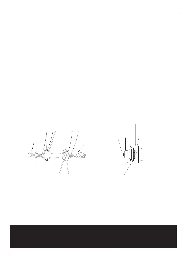
Remove axle nuts, washers, and axle retention device if fitted. The axle cone bearing
adjustment should permit smooth rotation of wheel. Cone locknut should be securely
fastened against axle cone to prevent loosening. Place the front wheel between the
fork blades with axle retention device and the projecting prongs of the retention device
securely fitting the slot in the fork or with standard washers securely placed in position
on to the wheel axle in the place of the retention washer. Replace locking washers and
nuts at both ends gradually and alternately in order to keep the wheel centered.
Caution:
Front wheel must be installed with retention devices securely placed into slots of fork
blades or washers if fitted. This will ensure positive locking of front wheel to front
fork.
Nut
Nut
Retention
device or washer
Retention
device or washer
Axle
Nut
Front Hub
Cone
Cone Locknut
Retention washer
(if fitted)
Front Fork
COTTERLESS CRANKS ADJUSTMENT
IMPORTANT
It is strongly recommended that the tightness of the nuts be checked after the first
two weeks of use and a maximum of three monthly intervals thereafter. Failure to do
so may cause permanent damage to the precision made components.
The adjustment should be made using a torque wrench fitted with a suitably sized
spanner having first removed the dust cap. Torque setting 38Nm (320 Ibs./ ins.) (30
lbs./ ft.)
BIKE CARE
STANDARD WHEEL ADJUSTMENT & REMOVAL
To Remove Rear Wheel
Move the chain onto the smallest rear sprocket. Disengage the brake quick release lever
if your bicycle is so equipped. Loosen both axle nuts by turning in a counter clockwise
direction. Pull the derailleur mechanism gear for additional clearance. Remove the rear
wheel by sliding forward and out of the frame.
To install wheel, locate the top section of the chain on the small sprocket and replace
the wheel into the frame by pushing back and centralising between the chainstays.
While holding the wheel in this position, tighten the axle nuts in a clockwise direction.
The wheel should turn freely and have very little side play.
Reset rear brake quick release mechanism and check brake for proper operation.
To Remove Front Wheel
Remove axle nuts, washers, and axle retention device if fitted. The axle cone bearing
adjustment should permit smooth rotation of wheel. Cone locknut should be securely
fastened against axle cone to prevent loosening. Place the front wheel between the
fork blades with axle retention device and the projecting prongs of the retention device
securely fitting the slot in the fork or with standard washers securely placed in position
on to the wheel axle in the place of the retention washer. Replace locking washers and
nuts at both ends gradually and alternately in order to keep the wheel centered.
Caution:
Front wheel must be installed with retention devices securely placed into slots of fork
blades or washers if fitted. This will ensure positive locking of front wheel to front
fork.
Nut
Nut
Retention
device or washer
Retention
device or washer
Axle
Nut
Front Hub
Cone
Cone Locknut
Retention washer
(if fitted)
Front Fork
COTTERLESS CRANKS ADJUSTMENT
IMPORTANT
It is strongly recommended that the tightness of the nuts be checked after the first
two weeks of use and a maximum of three monthly intervals thereafter. Failure to do
so may cause permanent damage to the precision made components.
The adjustment should be made using a torque wrench fitted with a suitably sized
spanner having first removed the dust cap. Torque setting 38Nm (320 Ibs./ ins.) (30
lbs./ ft.)


 To Next Page
 Loading...