OPERATOR'S
& MAINTENANCE
MANUAL
GP-6
SYSTEM
LAYOUT
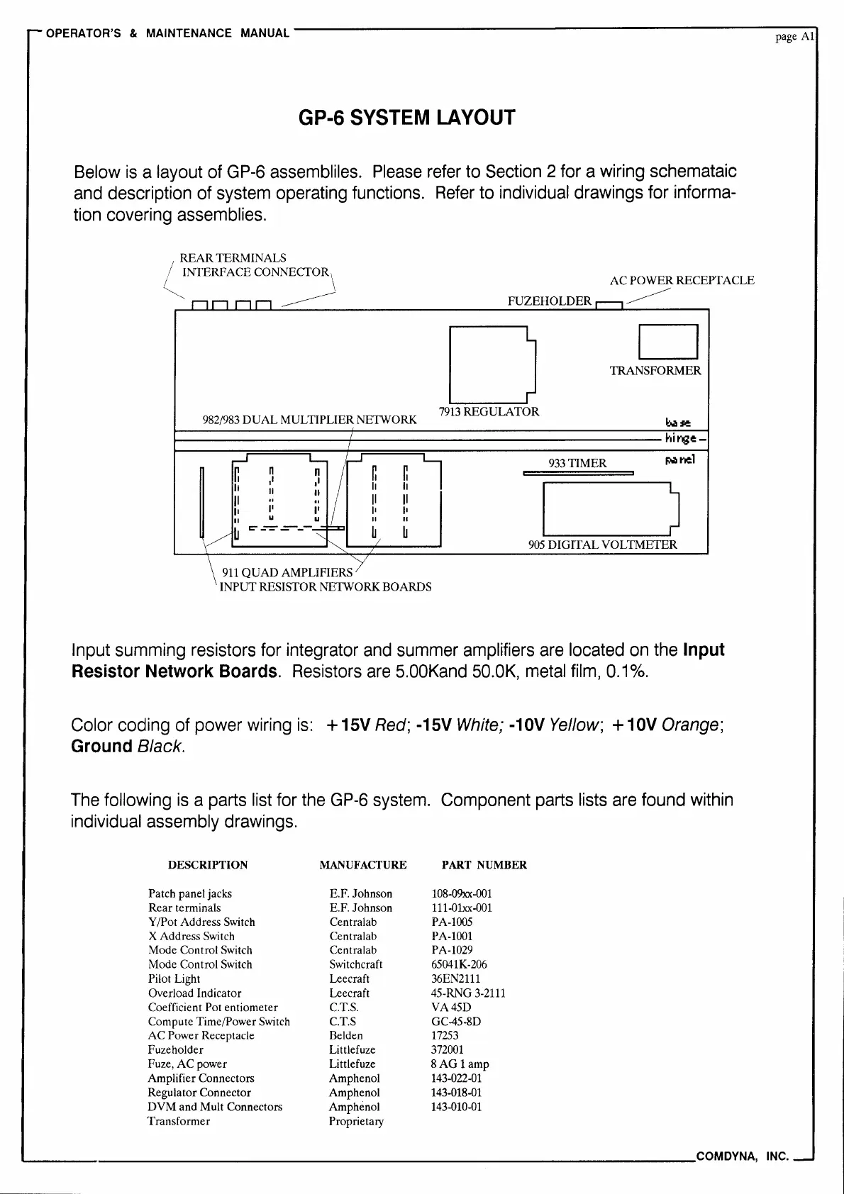
Below
is
a layout
of
GP-6
assembliles.
Please
refer
to
Section
2
for
a
wiring
schemataic
and
description
of
system
operating
functions.
Refer
to
individual
drawings
for
informa-
tion
covering
assemblies.
REAR
TERMINALS
INTERFACE
CONNECTOR\
-------
982/983
DUAL
MULTIPLIER
NETWORK
911
QUAD
AMPLIFIERS
AC
POWER
RECEPTACLE
FUZEHOLDER
D
D
TRANSFORMER
7913
REGULATOR
933
TIMER
Pi.I
nel
905
DIGITAL
VOLTMETER
INPUT
RESISTOR NETWORK BOARDS
Input
summing
resistors
for
integrator
and
summer
amplifiers
are
located
on
the
Input
Resistor
Network
Boards.
Resistors
are
5.00Kand
50.0K,
metal
film,
0.1
%.
Color coding
of
power
wiring
is:
+ 15V
Red;
-15V
White;
-10V
Yellow;
+ 10V
Orange;
Ground
Black.
The
following
is
a
parts
list
for
the
GP-6
system.
Component
parts
lists
are
found
within
individual
assembly
drawings.
DESCRIPTION
MANUFACTURE
PART
NUMBER
Patch panel jacks E.F. Johnson
108-09xx-001
Rear
terminals E.F. Johnson
111-01.xx-001
Y /Pot Address Switch Centralab PA-1005
X Address Switch Centralab
PA-1001
Mode Control Switch Centralab PA-1029
Mode Control Switch
Switchcraft 65041K-206
Pilot Light Leecraft 36EN2111
Overload Indicator
Leecraft 45-RNG
3-2111
Coefficient
Potentiometer
C.T.S.
VA45D
Compute Time/Power Switch C.T.S GC-45-8D
AC
Power Receptacle Belden
17253
Fuzeholder Littlefuze
372001
Fuze,
AC
power
Littlefuze
8AG
1 amp
Amplifier Connectors Amphenol 143-022-01
Regulator Connector Amphenol 143-018-01
DVM
and Mult Connectors Amphenol 143-010-01
Transformer Proprietary
page
Al
"----------------------------------------COM
DYNA,
INC.
 Loading...