OPERATOR'S
&
MAINTENANCE
MANUAL-----------------------------
page
A1
982/983
DUAL
MULTIPLIER
NETWORKS
The
982.2/983
board assemblies provide
two
independent multiplier
networks,
configured
so
that each,
when
used
with
an
external operational amplifier
may
be
programmed
as
a multiplier,
divider,
squarer
or
square root extractor.
Two
inputs
(Xin
and
Yin)
are multiplied
by
integrated circuit M
to
produce a
voltage
proportional
to
the
product
X*Y.
The
voltage
is
converted
to
a current
by
resistor
RS,
scaled
so
that
when
connected
to
the
summing
junction
of
a patch panel amplifier, and where
the
feedback
is
a standard
gain
1
SOK
ohm
resistor, the amplifier
will
produce a
full
scale
10
volts
output
with
10
volts
as
the
X and Y
inputs.
Adjustments
Each network
is
orginally
adjusted
at
the
factory.
The
networks
should,
however,
be
checked and readjusted,
if
necessary, during the initial checkout. Thereafter, the
networks
should be periodically checked
to
assure their
most
accurate operation. About
10
to
20
minutes should
be
allowed
for
warm-up
before adjusting.
Adjustment consists of zero
offset
balancing
(model
783
only)
and a trim
for
gain
and linearity. The suggested
procedures are
as
follows:
1.
Program
the
network
as
a
multiplier.
2.
With
inputs
X
and
Y
patched
to
ground,
adjust
potentiometer
Pz
for
a
zero
output.
Disregard
for
the
982.2
network.
3.
Program
an
integrator
as
a
ramp
function
to
sweep
from
minus
to
plus
1 o
volts
reference.
(For
convenience
make
all
adjustments
in
the
repetitive
operation
mode.)
Display
the
multiplier output
vs.
the
ramp
input.
Patch
the
ramp
to
the
Y
input;
the
X
input
should
remain
patched
to
ground.
Adjust
potentiometer
Px
until
a
best
zero
curve
is
obtained.
4.
Reverse
the
X
and
Y
inputs.
Adjust
potentiometer
Py
until
a
best
zero
error
is
obtained.
5.
Readjust
Pz
if
necessary.
6.
Patch
Reference
( + or-)
to
the
X
input
and
the
ramp
to
the
Y
input.
Sum
the
product
with
the
correct
polarity
of
the
ramp
to
display
an
error
curve.
Adjust
potentiometer
Pg
until
a
best
error
curve
is
obtained.
Reverse
the
X
and
Y
inputs,
recheck
and
readjust
if
necessary.
Check
the
error
curve
with
the
opposite
polarity
Reference
input
and
reverse
inputs
as
done
with
the
original
polarity.
Trim
potentiometer
Pg
until
a
best
compromise
of
error
curves
is
obtained
for
all
four
input
combinations.
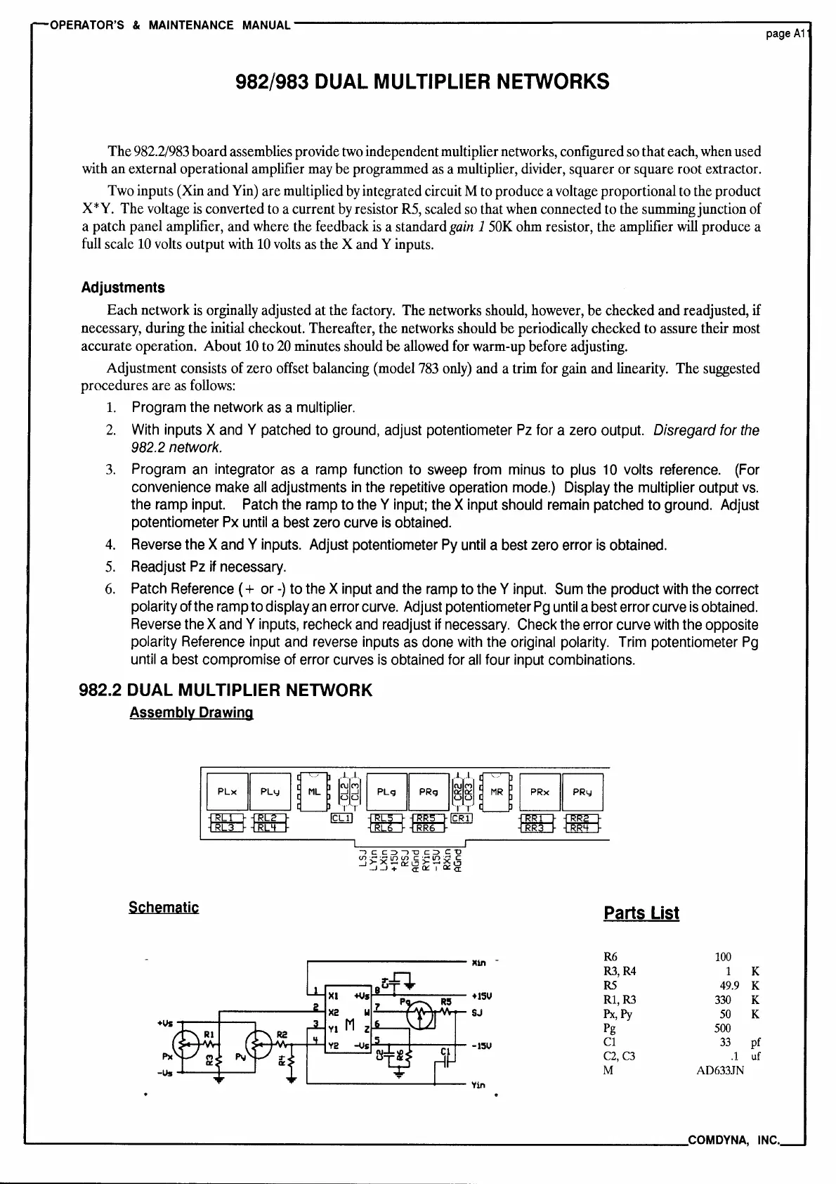
982.2 DUAL MULTIPLIER NETWORK
Assembly
Drawing
-,cc::,-,-oc::>C:-U
<.n·-·""l()(I)
c:·,..,l()·,.., C
_j>-X-~l?>-..-,Xl:J
_J_J+
a:~10::a:
Schematic
8litt
XI
+vs
p
X2
w
Vt
M
z
V2
-Vs
11111n
+15V
SJ
•1!5U
'l'in
Parts List
R6
100
R3,R4
1 K
RS
49.9
K
Rl,R3
330
K
Px,Py
50
K
Pg
500
Cl
33
pf
C2,C3
.1
uf
M
A0633JN
--------------------------------------COM
DYNA,
INC.
 Loading...