OPERA
TOR'S
& MAINTENANCE
MANUAL
----------------------------p-ag-e--,S.
U)
+'
;J
0,
+'
;J
0
H
(!)
.,.;
;t-!
.,..,
rl
P,
8
~
+
G0
+'
;J
p,
+'
:::5
0
H
(l)
+-'
(l)
s
0
•rl
+)
h
Q)
.p
0
ri,
GP-6
OPERATOR
FUNCTIONS
8
8
:::i
E-,
:::i
P-;
:::i
P-;
8
c:1
P-;
Z
:::i
Z 8
"-
8
H
:::i
p.,
i:r:
8
Figure
2-1
REAR
TERMINALS
H
o
23 23
µ.:J
:::i
8 0
ADDRESS
8
---------..
7------
X
ADDRESS
~
------+-+-+-+--1-----
5
--+-,r---~1~++-+---++-----.
4 ' '
p.,
P-;
i:r:
r:Q~OOC.,><:
~
;,-,
MODE
SELECTOR
~:~~TifrW
1
I
Hold
Inhibit,
Amp.
pin
51
Time
Base,
Timer
pin
17
-Internal
Readout
Meter
rCTP,
Timer
pin
1
;-j~
~
'.
j /
-0
n
c
~
'--------,
..
--0J
~
l
COMPUTE
TIMl
.__
_____
---()::
1(
>-+----
0 0
0---
01
FI
i
0
----+--+--4--------1--....-...1,......+-,____i.
_
_.......l
\
~-
::~
IOOK.
'----~,
10
4
8
7
7
(,,
5
3-~
l.
I
N
6
o
~)=-
8-
~
--o
6
-
-0
o-
Y)
Q
~'o
rr
?
? •
7
I
I
,.I,
I
I-
h
h
•rl
•rl
,,
0,
P-<N
H
h
(1)
P,·rl
s
8
P,
•rl
~
E-i
H
- Q)
-
:>,
s
1-:,
rn
·ri
(/)
,-1
E-;
())
I I I
~
h5,e-V
\-=
I
J
00
I\
/
'Dq{
2
0,
0:::
f::;
h
~
QJ
H
r'1
pi
cu
p
8
C)
MODE
CONTROL
CUEFFIC
ENT
PO'l'EN'I'IU1vu::<;11:.,l-<
Slow Time
In,
Timer
pin
20-
Rep
•
CU,
Tj
rnr;r 1
9----------'
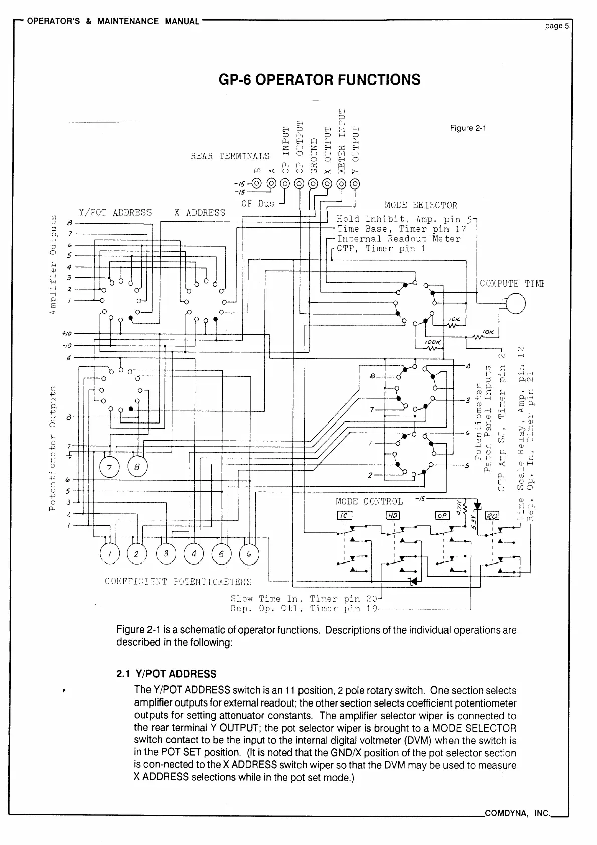
Figure
2-1
is
a schematic
of
operator functions. Descriptions
of
the
individual operations
are
described
in
the following:
2.1
Y/POT
ADDRESS
The
Y/POT
ADDRESS
switch
is
an
11
position, 2 pole rotary switch.
One
section selects
amplifier outputs for
external
readout;
the other section selects coefficient potentiometer
outputs for setting attenuator constants.
The
amplifier selector wiper
is
connected
to
the
rear
terminal Y
OUTPUT;
the
pot selector wiper
is
brought to a
MODE
SELECTOR
switch contact to
be
the
input to
the
internal
digital voltmeter
(DVM)
when
the
switch
is
in
the
POT
SET
position.
(It
is
noted
that
the
GND/X
position
of
the pot selector section
is
con-nected to
the
X
ADDRESS
switch wiper
so
that the
DVM
may
be
used
to
measure
X
ADDRESS
selections while
in
the
pot
set
mode.)
u
(/)0
--------------------------------------COM
DYNA,
INC.
 Loading...