Do you have a question about the Comelit Simple Key SK9000I and is the answer not in the manual?
General safety instructions for installation and use of the device, adhering to standards and manufacturer guidelines.
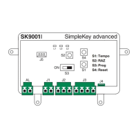
Overview of the SK9000 unit, its components, terminals, programming modes, and timer adjustment.
Steps for managing master and user tokens, including adding, resetting, and deleting.
Understanding unit LED status for normal operation and basic troubleshooting.
Details on opening time, output, power consumption, operating temperature, voltage, and dimensions.
Illustrations showing the installation of the unit with Powercom Art. 3329.
Illustrations showing the installation of the unit with Vandalcom Art. 3179.
Illustrations showing the installation of the unit with Icom Art. 3349.
Illustrations showing the installation of the unit with Art. 3330.
Illustrations showing the installation of the unit with Art. SK9040.
Detailed physical dimensions of the SK9000 unit with measurement callouts.
Schematic showing the basic electrical connections for the SK9000 unit.
Note on the necessity of a separate power supply for the electric lock.
Wiring diagram for SK9000 connected to a Powercom Simplebus system.
Wiring diagram for SK9000 connected to a Vandalcom Simplebus system.
Wiring diagram for SK9000 connected to an Icom Simplebus system.
| Category | IP Access Controllers |
|---|---|
| Model | SK9000I |
| Manufacturer | Comelit |
| Connectivity | Ethernet |
| User Capacity | 1000 users |
| Protection Rating | IP65 |
| Mounting | Surface mount |
| Current Consumption | Max 500 mA |
| Weight | 150 g |
| IP Rating | IP65 |
| Communication | TCP/IP |
| Power Supply | 12V DC |
| Access Control Protocols | Wiegand |
| Operating Voltage | 12-24 VDC |
| Humidity | 10% to 90% RH |
| Compatibility | Comelit |