-------------
-------~--------------------------.
APPENDIXF
SERIAL INTERFACE INFORMATION
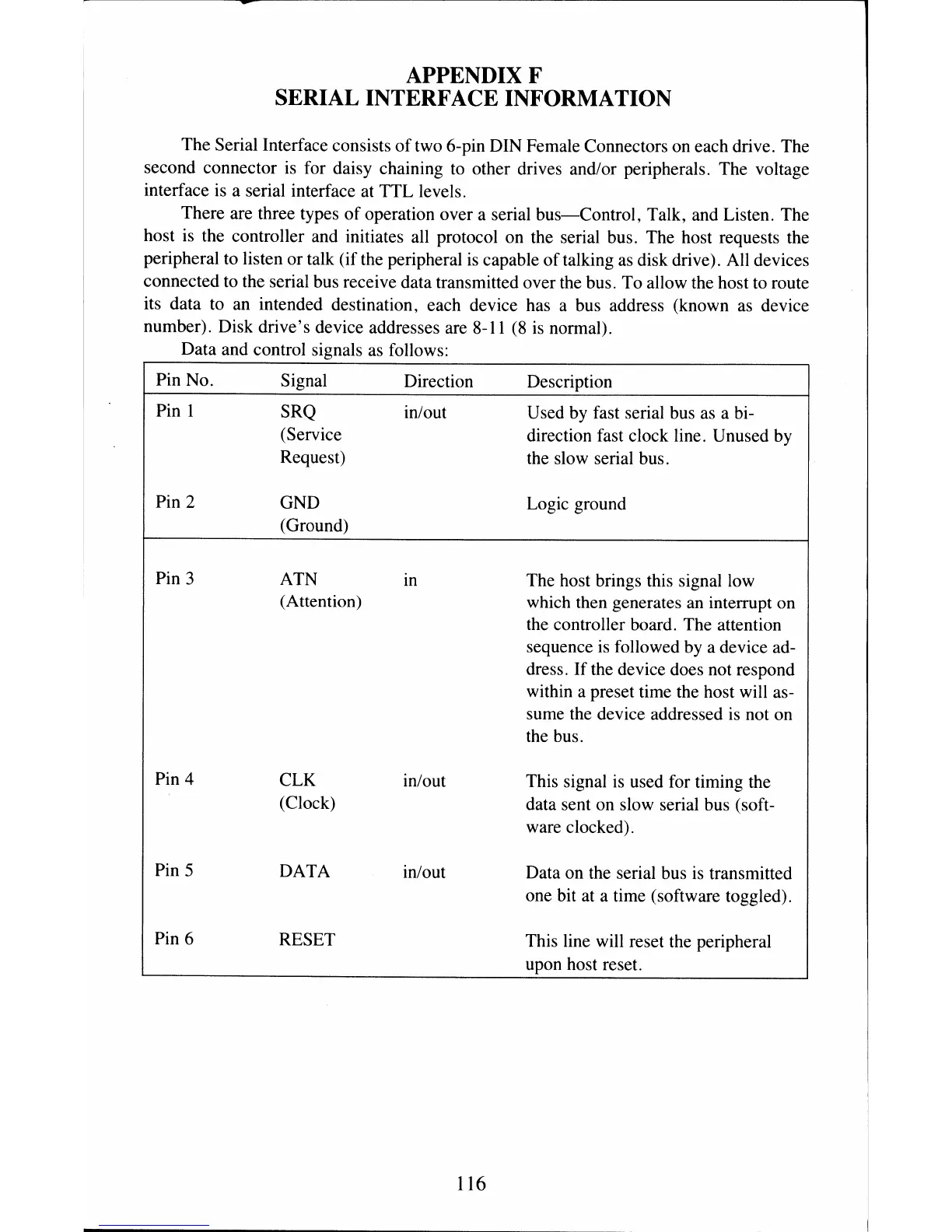
The Serial Interface consists
of
two 6-pin DIN Female Connectors on each drive. The
second connector is for daisy chaining to other drives and/or peripherals. The voltage
interface is a serial interface at
TTL
levels.
There are three types
of
operation over a serial
bus-Control,
Talk, and Listen. The
host is the controller and initiates all protocol on the serial bus. The host requests the
peripheral to listen
or
talk (if the peripheral
is
capable
of
talking as disk drive). All devices
connected to the serial bus receive data transmitted over the bus. To allow the host to route
its data to an intended destination, each device has a bus address (known as device
number). Disk
drive's
device addresses are 8-11
(8
is normal).
Data and control signals as follows:
---------------------------------------,
Pin No.
Pin
1
Pin 2
Pin 3
Pin 4
Pin 5
Pin 6
Signal
SRQ
(Servic
e
t)
Reques
GND
(Groun
d)
ATN
(Attent
ion)
CLK
(Clock
DATA
RESET
Direction
in/out
In
in/out
in/out
116
Description
Used by fast serial bus as a bi-
direction fast clock line. Unused by
the slow serial bus.
Logic ground
The host brings this signal low
which then generates an interrupt on
the controller board. The attention
sequence is followed by a device ad-
dress.
If
the device does not respond
within a preset time the host will as-
sume the device addressed is not on
the bus.
This signal is used for timing the
data sent on slow serial bus (soft-
ware clocked).
Data on the serial bus is transmitted
one bit at a time (software toggled).
This line will reset the peripheral
upon host reset.
 Loading...