1571/C128D ALIGNMENT/REPAIR TEST
VERSION 1.2.1
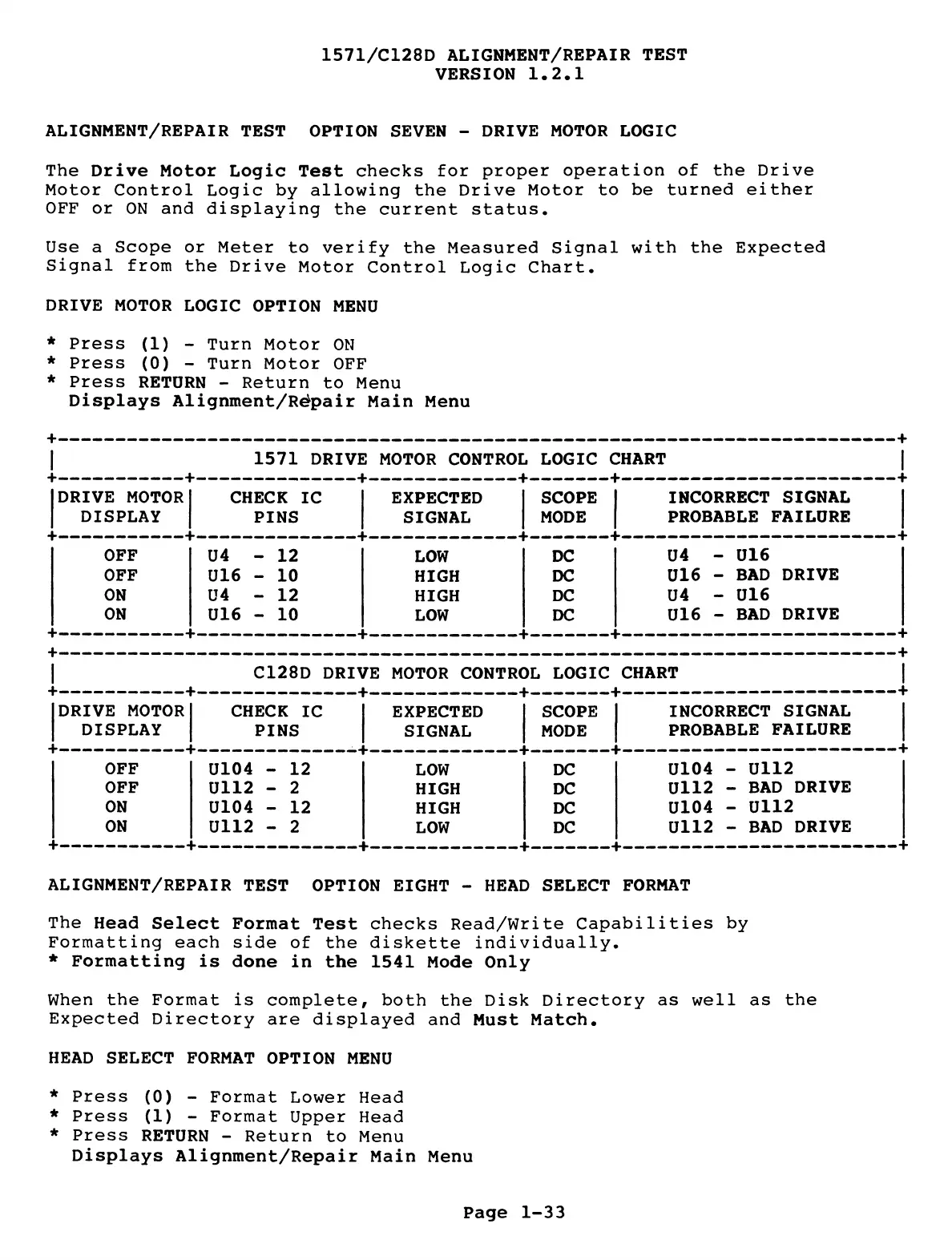
ALIGNMENT/REPAIR TEST OPTION SEVEN - DRIVE MOTOR LOGIC
The Drive Motor Logic Test checks for proper operation of the Drive
Motor Control Logic by allowing the Drive Motor to be turned either
OFF or ON and displaying the current status.
Use a Scope or Meter to verify the Measured Signal with the Expected
Signal from the Drive Motor Control Logic Chart.
DRIVE MOTOR LOGIC OPTION MENU
* Press (1) - Turn Motor ON
* Press (0) - Turn Motor OFF
* Press RETURN - Return to Menu
Displays Alignment/Rdpair Main Menu
+---------------------------------------------------------------------------------------+
| 1571 DRIVE MOTOR CONTROL LOGIC CHART |
+
------------
+
----------------
+
---------------
+
--------
+
----------------------------
+
DRIVE MOTOR
DISPLAY
CHECK IC
PINS
EXPECTED
SIGNAL
SCOPE 1 INCORRECT SIGNAL
MODE 1 PROBABLE FAILURE
OFF
U4 - 12
LOW
DC
U4 - U16
OFF
U16 - 10
HIGH DC
U16 - BAD DRIVE
ON
U4 - 12
HIGH DC
U4 - U16
ON
U16 - 10
LOW DC
U16 - BAD DRIVE
+
------------
+
----------------
+
---------------
+
--------
+
------
+----------------------------------------------------------------
I C128D DRIVE MOTOR CONTROL LOGIC CHART
DRIVE MOTOR
DISPLAY
CHECK IC
PINS
EXPECTED
SIGNAL
SCOPE
MODE
INCORRECT SIGNAL
PROBABLE FAILURE
OFF
U104 - 12
LOW DC
U104 - U112
OFF
U112 - 2
HIGH DC
U112 - BAD DRIVE
ON
U104 - 12
HIGH
DC
U104 - U112
ON
U112 - 2
LOW DC
U112 - BAD DRIVE
ALIGNMENT/REPAIR TEST OPTION EIGHT - HEAD SELECT FORMAT
The Head Select Format Test checks Read/Write Capabilities by
Formatting each side of the diskette individually.
* Formatting is done in the 1541 Mode Only
When the Format is complete, both the Disk Directory as well as the
Expected Directory are displayed and Must Match.
HEAD SELECT FORMAT OPTION MENU
* Press (0) - Format Lower Head
* Press (1) - Format Upper Head
* Press RETURN - Return to Menu
Displays Alignment/Repair Main Menu
Page 1-33
+ +
 Loading...