Ruckus ICX 7450 Switch Hardware Installation Guide 55
Part Number: 53-1003899-09
Figure 43 shows the LEDs on the Ruckus ICX 7450-24P front panel. The up-arrow port status LEDs for the 1 GbE ports correspond to
the upper, odd-numbered ports; the down-arrow port status LEDs correspond to the lower, even-numbered ports.
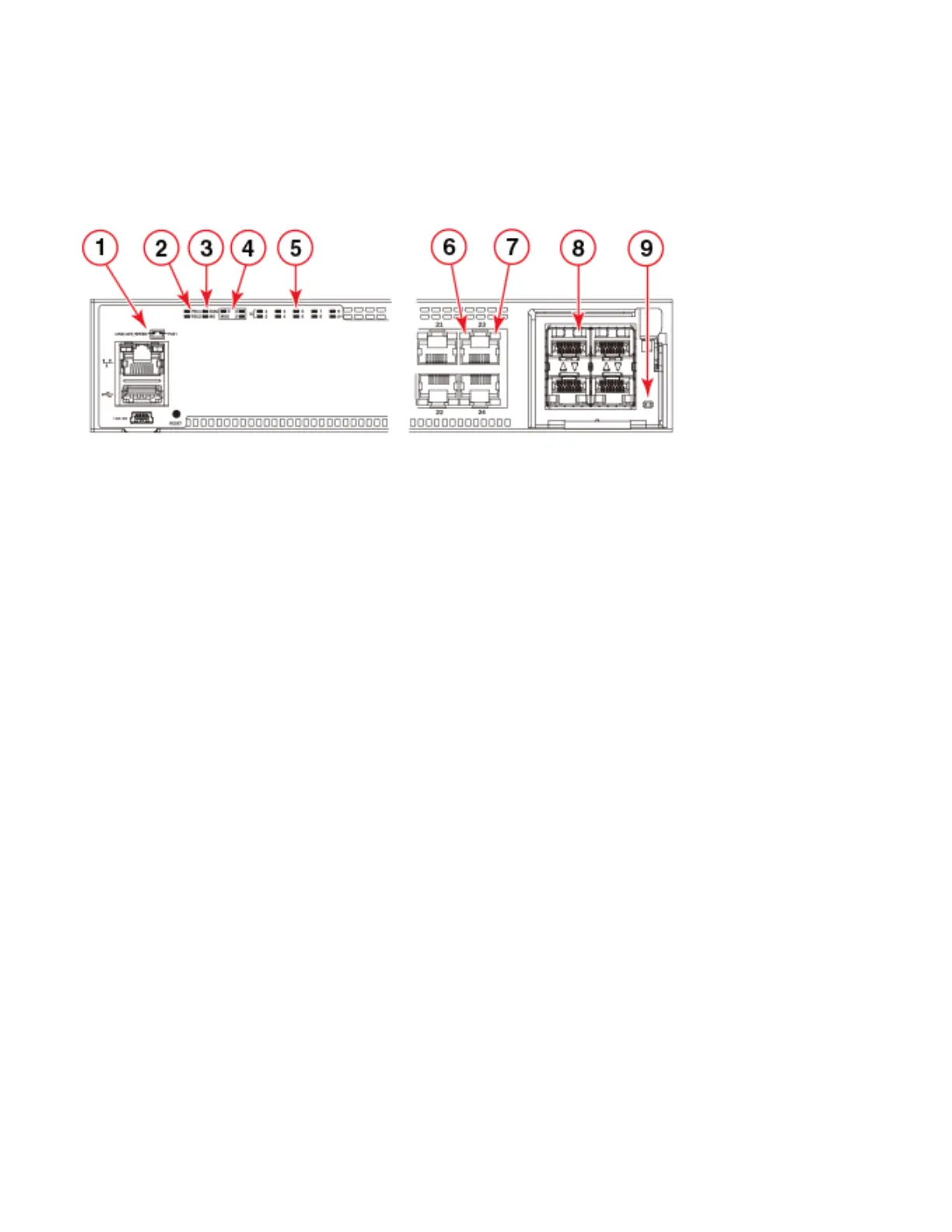
FIGURE 43 Ruckus ICX 7450-24P front-panel LEDs
PoE/PoE+ power is available to ports 1-24. High PoE/PoH is limited to ports 1-8.
The Ruckus ICX 7450-32ZP has the following LEDs on the front panel:
• Two management port status LEDs (green) for speed and link/activity
• Two power supply unit (PSU) bicolor status LEDs (green and amber) labeled PSU1 and PSU2
• One DIAG (diagnostic) bicolor status LED (green and amber)
• One MS (stacking configuration) bicolor status LED (green and amber)
• Three MOD (media expansion module) monocolor status LEDs (green)
• Ten stack ID (stack identifier) monocolor indicator LEDs (green)
• 24 1 GbE port bicolor status LEDs for ports 1-24 (green for 1 GbE and amber for 10/100 Mbps Ethernet) which indicate 1
GbE or 10/100 Mbps Ethernet mode of operation
• 8 2.5 GbE port bicolor status LEDs for ports 25-32 (green for 2.5 GbE and amber for 100/1000 Mbps Ethernet) which
indicate 2.5 GbE, 1 GbE, or 100 Mbps Ethernet mode of operation
• 32 PoE+ port monocolor status LEDs (green for providing power to attached device)
1 Management port speed and link/activity LEDs 6 Ports 1-24 speed and link/activity LEDs
2 PSU1 and PSU2 status LEDs
PSU1 corresponds to the right power supply slot
on the rear panel and PSU2 to the left power
supply slot, as viewed from the rear.
7 PoE power LEDs. The PoE indicator is on if a port is
providing power to the connected device, and off if it
is not supplying power.
3 DIAG (diagnostic) status LED and MS (stacking
configuration) status LED
8 MOD2 1/10 GbE module speed andlink/activity
LEDs
4 MOD (media expansion module) LEDs. Module 2
is located on the right side of the front panel.
Module 3 and 4 are the right and left stacking
modules on the rear panel, as viewed from the rear.
9 MOD2 1/10 GbE power LED
5 Stack ID LEDs
Indicates stack unit identifier (1-12).
 Loading...