Base Load Sequencing (BLS) 10
October 2013 GB 73 /80
Digital output "Remote load"
Do not use this output to switch the compressor on
and off.
This output switches the compressor on load. This
remote load signal should be active when the "Re-
mote load enabled" output is sent to the compres-
sor controller.
Digital output "Remote half-load"
This output is not used for this application.
Connection allocation and connection
examples
Connection allocation
Port Function
6 COM
7 110...230 V UC
8
Digital input "Oper-
ating"
24...48 V UC
9 COM
10 110...230 V UC
11
Digital input "Motor"
24...48 V UC
12 COM
13 110...230 V UC
14
Digital input "On-
Load"
24...48 V UC
16 (~) (+)
17
Power supply
110...230 V AC/DC
(±)10%
(~) (-)
21 COM
22 NC
23
Digital output
"Remote load
enabled"
NO
26 COM
27 NC
28
Digital output
"Remote load"
NO
31 COM
32 NC
33
Digital output
"Remote half-load"
NO
Chart 10-11: Connection allocation
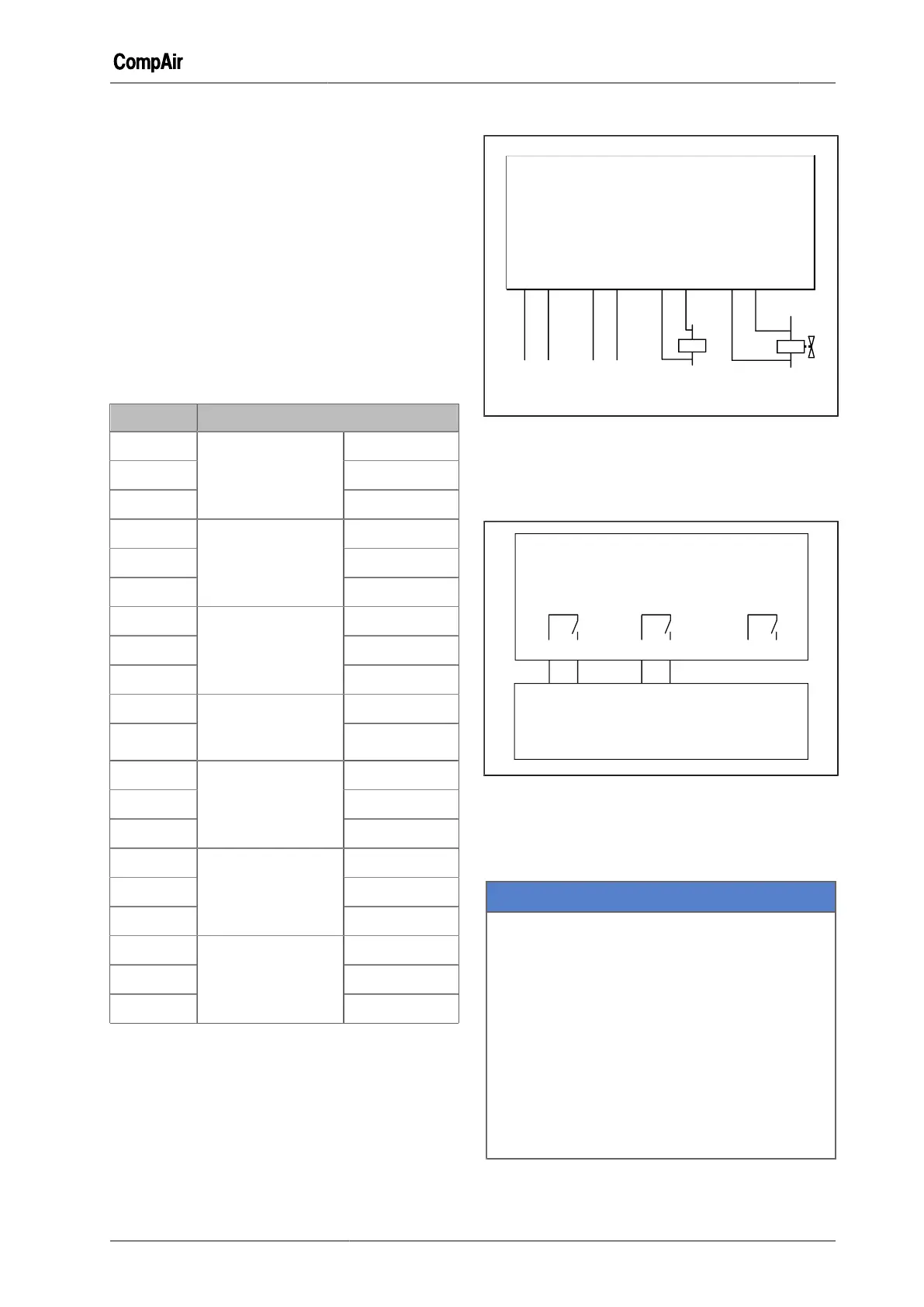
Compressor Status Messages
Fig. 10-18: Connections for status messages
Controlling a compressor with line pressure
sensor and electronic compressor controller
(example)
Electronic compressor controller
Fig. 10-19: Line pressure sensor and electronic com-
pressor controller
Controlling a compressor with line pressure
switch (example)
NOTICE
Material damage
When a compressor module (STD) is installed,
the compressor's pressure switch can, under
certain circumstances, no longer provide over-
pressure protection.
➯
For compressors that are not equipped with
independent over-pressure detection, we
recommend that a pressure switch be incor-
porated in the compressor fault circuit(s) to
ensure that any local over-pressure condi-
tion will stop the compressor independently
from the DELCOS XL Master.
 Loading...