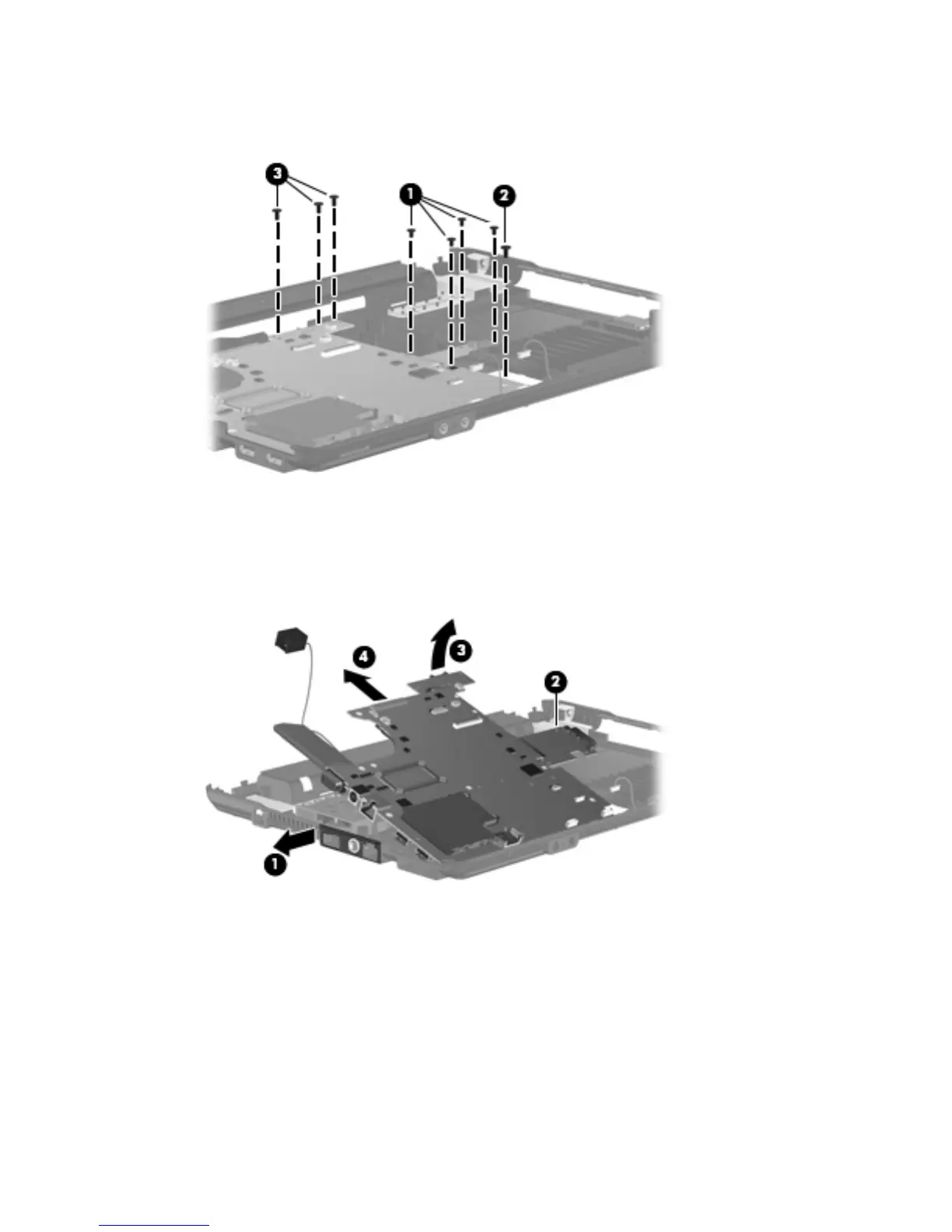
3. Remove the three Torx 6.0-mm screws (3) that secure the battery connector board to the base
enclosure.
4. Flex the left side of the base enclosure until the external monitor connector (1) and the heat sink
(2) are clear of the openings in the base enclosure.
5. Lift the rear edge of the system board (3) until it rests at an angle.
6. Remove the system board (4) from the base enclosure by sliding it back.
Reverse the preceding procedure to install the system board.
Component replacement procedures 69
 Loading...