Maintenance & Service Guide
Presario 5700 Series Personal Computers
Models: 5710, 5711, 5712, 5714, 5715, 5716, 5717, 5718, 5721,
5722, 5724, 5726, 5728, 5733, 5735, 5736, 5738, 5745 and 5746
MSG Index | Home | Preface | Product Description | Troubleshooting | Illustrated Parts |
Removal & Replacement | Jumpers & Switches | Specifications | Connector Pins
Removal and Replacement
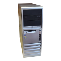
Back I/O Panel
Back I/O Panel may vary depending on model. Pentium III model shown.
Disassembly
Sequence
Chassis
Mass Storage Devices
Button Board
Front I/O Cable
Creativity Action Center
Fan
Option Card Retainer
Removal
1. Perform the preparation for
disassembly procedures.
2. Remove the Chassis.
3. Disconnect Baffle from Fan.
4. Remove Graphics Board (On select
models only).
5. Remove the Fax/Modem.
6. Remove Networking Interface Card
(on select models only).
7. Remove Memory.
8. Remove Processor.
9. Disconnect System Board Cables.
10.Remove the System Board.
11.Push the Back I/O Panel into the
chassis from the rear of the chassis
and remove.
Replacement
http://www.compaq.com/athome/support/msgs/5700/iopanel.html (1 of 2) [1/10/2002 11:55:52 AM]

 Loading...