Do you have a question about the Competition 50HPRA-E and is the answer not in the manual?
Report shipping damage immediately to the carrier and examine for signs.
Ensure electricity supply and minimum water circulation (6 m³/h) before starting.
Press SET and buttons simultaneously for 5 seconds to enter programming.
Chart detailing functions, ranges, codes, and how to modify values.
Protects compressor from overpressure, often due to low water flow.
Protects compressor from frequent starts due to low refrigerant or low ambient temp.
Shuts down unit if water flow is insufficient or absent.
5-minute delay prevents compressor overload during startup attempts.
Check electrical breaker, water flow, and bypass valve status.
Check time delay, desired temperature setting, and thermostat programming.
Indicates potential temperature sensor issue; contact dealer.
Indicates potential automatic defrost sensor issue.
Lists causes like high pressure, high water temp, loss of refrigerant.
Ensure supervision, avoid obstructions, proper compliance, etc.
Manufacturer disclaims responsibility for accidents from unsafe installation.
Not for persons with reduced capabilities unless supervised; keep children away.
Press the button to start. Press again to stop operation.
Use SET and ▲/▼ buttons to set desired water temperature.
Ensure electricity supply and minimum water circulation (6 m³/h).
Setting thermostat high doesn't heat faster than desired point.
List of available spare parts with their part numbers.
Steps to prepare the unit for the start of the swimming season.
Steps for draining and preparing the unit for winter storage.
Choose a quiet, stable location with adequate space around the unit.
Install on a solid base with absorbent pads to minimize vibrations.
Regular filter cleaning, coil maintenance, and unit cleaning for best performance.
Always turn off electricity at the breaker before performing any maintenance.
Install check valve/loop above chlorinator to prevent chlorine backup.
Maintain 6-15 m³/h flow; consider bypass for service.
Fasten unit securely to the concrete pad using TAPCON screws.
Normal condensation drains; locate direct and winterizing drains.
Ensure correct water flow and proper electrical grounding for operation.
Improper electrical grounding can void the warranty.
Illustrates sequence: Pool, Pump, Filter, Heater, Chemical Loop, Chlorinator.
Qualified installer, specific wire cert, exclusive circuit, proper grounding required.
Table of model-specific electrical ratings, current, protection, conductors.
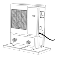
Connect cables as per wiring diagram inside the unit's top cover.
Install a disconnect switch near the unit for easy power disconnection.
Operating with improper voltage or phase imbalances abuses the unit.
Disengage main power disconnect before attempting installation.
Connect all cables as shown in the wiring diagram inside the unit.
Install a power interruptor near the unit for easy current cutoff.
Avoid operating with incorrect line voltage or phase fluctuations.
Cut main power at the switch before starting installation.
Provides a comprehensive wiring diagram for the heat pump unit.
Table of electrical ratings, voltage, current, protection, conductors for models.
Ensure proper water circulation (6-15 m³/h) and open valves.
Connect all metal components to ground for safety.
Illustrates sequence: Pool, Pump, Filter, Heater, Chemical Loop, Chlorinator.
Detachable unions are vital for servicing and winterizing.
Install check valve/loop above chlorinator to prevent chlorine backup.
Maintain 6-15 m³/h flow; exceeding 15 m³/h may damage unit.
Mount unit on a concrete slab using TAPCON screws and washers.
Normal condensation drains; check direct and winterizing drains.
Choose a quiet location away from neighbors, on a flat, stable surface.
Maintain specified distances around the unit for airflow.
Install on a solid base, using absorbent pads to minimize vibrations.
Backwash filter, keep coil clean, clean unit with mild cleaner.
Turn off electricity at the breaker before performing any maintenance.
Check electrical breaker, water flow, and bypass valve.
Check time delay, desired temperature setting, and thermostat programming.
Indicates potential temperature sensor issue; contact dealer.
Indicates potential automatic defrost sensor issue.
Lists causes like high pressure, high water temp, loss of refrigerant.
Protects compressor from overpressure, usually due to low water flow.
Protects compressor from frequent starts due to low refrigerant or low ambient temp.
Shuts down unit if water flow is insufficient or absent.
5-minute delay prevents compressor overload during startup attempts.
Expresses gratitude for purchase and satisfaction with product.
Fields to record model, serial number, purchase/installation dates, dealer info.
Press SET and buttons simultaneously for 5 seconds to enter programming.
Chart detailing functions, ranges, codes, and how to modify values.
Default values should not be modified without dealer authorization.
5-year parts, 1-year labor warranty; compressor also covered for 5 years.
Lists items not covered, e.g., normal maintenance, faulty installation, misuse.
Read troubleshooting section first; contact authorized dealer for service.
Ensure the heat pump is supplied with electricity.
Verify filtration pump operates with 6 m³/h minimum water circulation and 3 BARS pressure.
If conditions not met, digital display thermometer will be unusable.
| Brand | Competition |
|---|---|
| Model | 50HPRA-E |
| Category | Swimming Pool Heater |
| Language | English |