024-55560
3
9. Re-install the primary drive assembly per factory service manual instructions.
10. Check the sprocket alignment per factory service manual instructions. Torque the
compensating nut to the engine manufacturer’s specifications. NOTE: Use Loctite
262 (red) on the threads of the compensating nut.
11. Re-install the primary cover using a new gasket and fill the primary case with the
correct amount of oil.
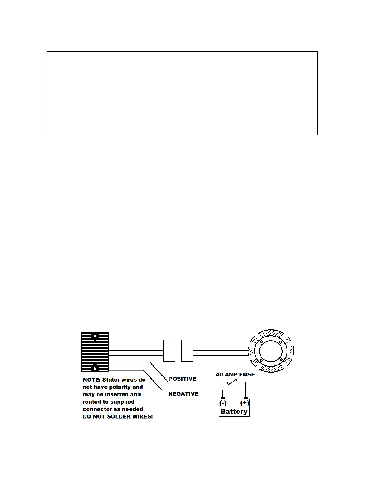
12. Attach the Compu-Fire 3 Phase Voltage Regulator to the frame. NOTE: The voltage
regulator must be mounted in an area with good air flow. Install the three wire
connector on the stator wires. NOTE: Stator wires have no polarity. Connect it to the
voltage regulator. Route the wires marked (+) and (-) to the battery. CAUTION! Use
the wire ties supplied to secure the wires to the frame. Make sure the wires cannot
come in contact with the exhaust system or become pinched between moving parts.
13. Connect the (+) wire from the voltage regulator to one side of the fuse holder. Do not
shorten the (+) wire or change the factory-crimped terminal. NOTE: If the cable is too
long, it must be coiled up and secured in the battery compartment. Do not shorten
the cable or change the terminal. Connect the other side of the fuse holder to the (+)
terminal of the battery. Connect the wire marked (-) to the (-) terminal of the battery.
Install the 40 amp fuse.
14. Reconnect the battery cables removed in step 1. Start the engine and allow it to
warm up to where it will idle. Verify the correct charging system output.
ORIGINAL EQUIPMENT COMPONENTS
4. Shaft extension
5. Compensating sprocket
6. Sliding cam
7. Compensating sprocket cover
8. Shim washer (varying thickness)
9. Compensating nut.
 Loading...