12
7
8
9
10
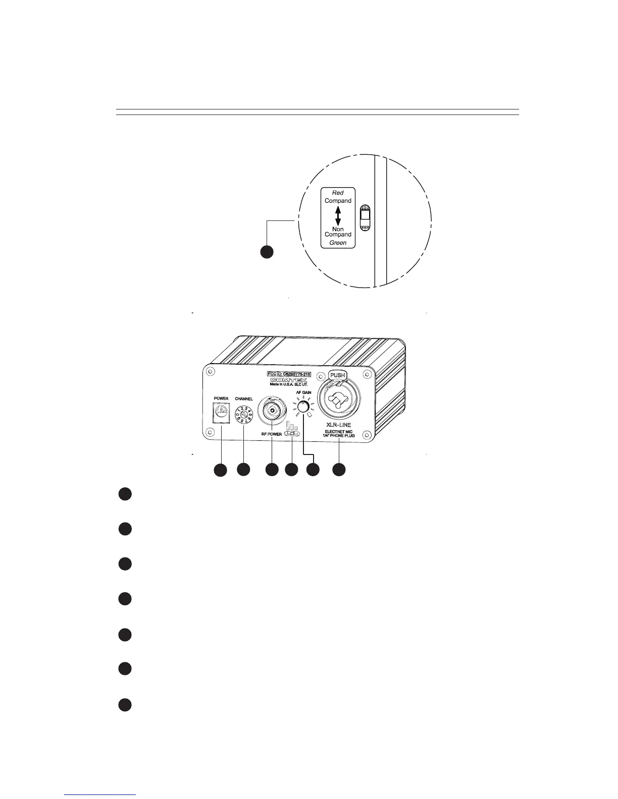
BST 75-216 REAR PANEL
DC INPUT JACK: Requires 12V DC at 200 mA source.
(Positive or negative center pin.)
CHANNEL SELECTOR SWITCH: Selects the frequency on which the
transmitter will operate. (See Frequency Information Section.)
EXTERNAL ANTENNA JACK: BNC connector provides a standard
50 ohm RF output for use with an external antenna.
RF POWER SWITCH: Adjusts the RF power output of the transmitter
(High-100 mW, Mid-50 mW, Low-25 mW).
AUDIO LEVEL CONTROL: This control is used to set the proper
modulation level when referenced with the VU meter.
MIC / LINE AUDIO INPUT: XLR-3 accepts balanced line level input.
1/4” phone jack accepts AUX input or 2-conductor electret microphone.
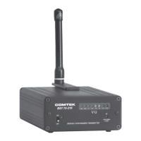
COMPAND / NON COMPAND SWITCH: For high fidelity operation,
switch must be in compand position when using companded receivers
and in non-companded position when using non-companded receivers.
11
Page 7
7
109 12
8
11
13
13
Located on
bottom of
transmitter