ESPAÑOL
DEUTSCH
РУССКИЙ
ITALIANO ENGLISH
FRANÇAIS
FRATELLI COMUNELLO S.P.A. AUTOMATION GATE DIVISION
Via Cassola, 64 - C.P. 79 36027 Rosà, Vicenza, Italy | Tel. +39 0424 585111 Fax +39 0424 533417 | info@comunello.it comunello.com
AVVERTENZE
Il presente manuale di installazione è rivolto esclusivamente a personale
professionalmente competente. Tutto quello che non è espressamente
previsto in queste istruzioni non è permesso. In particolare è importante
prestare attenzione alle seguenti avvertenze:
• Vericare che la tensione di alimentazione sia uguale a quella
presente nei morsetti della scheda.
• Togliere tensione prima di effettuare i collegamenti elettrici.
DESCRIZIONE DEL PRODOTTO E DESTINAZIONE D’USO
La fotocellula DART SLIM con elettronica semplice ed efcace, si addice
ad ogni tipo di impianto e condizione.
VERIFICHE PRELIMINARI
• Vericare che il prodotto all’interno dell’imballo sia integro ed in
buone condizioni.
• Vericare che il luogo di posizionamento delle fotocellule consenta
una corretta installazione e ssaggio delle fotocellule stesse.
INSTALLAZIONE
• Aprire la fotocellula e allacciare i cavi alla morsettiera secondo
schema del paragrafo “collegamenti elettrici”.
• Allineare il trasmettitore con il ricevitore (il ricevitore è munito di una spia
interna rossa che si spegne quando le due fotocellule sono allineate).
• Dopo aver forato la scatola ai quattro angoli ssare le fotocellule alla
parete (FIG. 1) o alla colonnina (FIG. 2).
• Utilizzare sistemi di ssaggio adeguati al tipo di montate (ssaggi non inclusi).
COLLEGAMENTI ELETTRICI
Funzionamento con trasmettitore e ricevitore contrapposti. Doppio relè
di sicurezza.
Trasmettitore:
• Frequenza modulazione: 330 Hz
• Lunghezza d’onda dell’emissione infrarossa: 950 nm
• J1: 2-3 per alimentazione a 12V
• J1: 1-2 per alimentazione a 24V (FIG. 3)
Ricevitore:
• Portata contatti relè: 1A max a 30 VDC
• Uscita contatto normalmente aperto: NA
• Uscita contatto normalmente chiuso: NC
• Led rosso che si spegne con le fotocellule allineate
• J1: 1-2 Se alimentazione a 12V / 2-3 se alimentazione a 24V (FIG.3)
• Portata massima in condizioni ottimali: 18m
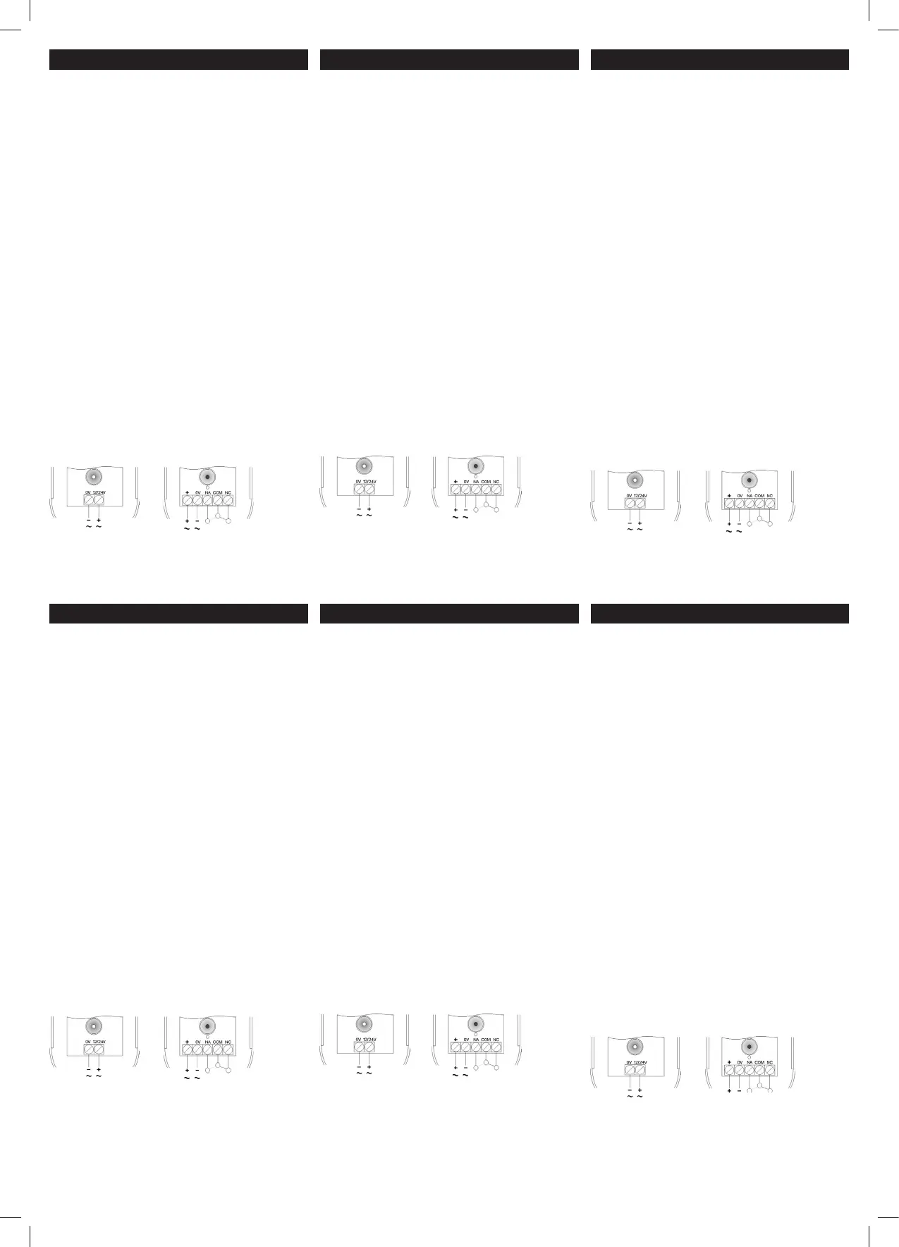
Collegamenti elettrici
• Aprire la scatola della fotocellula come descritto nel capitolo
installazione e allacciare i cavi alla morsettiera secondo
schema seguente:
TRASMETTITORE RICEVENTE
SMALTIMENTO
Alcuni componenti del prodotto possono essere riciclati mentre
altri come ad esempio i componenti elettronici devono essere
smaltiti secondo le normative vigenti nell’area di installazione. Alcuni
componenti potrebbero contenere sostanze inquinanti e non devono
essere dispersi nell’ambiente.
AVERTISSEMENT
Ce manuel d’installation s’adresse exclusivement à un personnel
compétent. Toutes les opérations non expressément prévues dans ces
instructions sont interdites Il est en particulier indispensable de respecter
les consignes suivantes:
• Vérier que la tension d’alimentation est identique à celle des bornes
de la carte.
• Sectionner la tension avant de procéder aux branchements électriques.
DESCRIPTION DU PRODUIT ET APPLICATION
La photocellule DART SLIM utilise un système électronique simple et
efcace adapté à tous les types d’installations et de conditions.
CONTRÔLES PRÉLIMINAIRES
• Vérier que le contenu de l’emballage est en parfait état.
• Vérier que les photocellules sont xées sur une surface solide et
adaptée à ces dernières.
INSTALLATION
• Ouvrir la photocellule et brancher les câbles au bornier selon le
schéma du paragraphe «Branchements électriques».
• Aligner l’émetteur et le récepteur (le récepteur comprend un voyant
interne rouge qui s’éteint si les deux photocellules sont alignées).
• Après avoir percé le boîtier aux quatre angles, xer les photocellules
au mur (FIG. 1) ou à la colonne (FIG. 2).
• Utiliser des systèmes de xation adaptés au montant (non inclus).
BRANCHEMENTS ÉLECTRIQUES
Fonctionnement avec émetteur et récepteur opposés l’un à l’autre.
Double relais de sécurité.
Émetteur:
• Fréquence modulation: 330 Hz
• Longueur d’onde de l’émission infrarouge: 950 nm
• J1: 2-3 pour alimentation à 12V
• J1: 1-2 pour alimentation à 24V (g.3)
Récepteur:
• Portée contacts relais: 1A max. à 30 VCC
• Sortie contact normalement ouvert: NO
• Sortie contact normalement fermé: NF
• Led rouge qui s’éteint avec les photocellules alignées
• J1: 1-2 si alimentation à 12V / 2-3 si alimentation à 24V (g.3)
• Portée max. en conditions optimales: 18m
Branchements électriques
• Ouvrir le boîtier de la photocellule (voir le chap. Installation) et
brancher les câbles au bornier selon le schéma suivant.
ÉMETTEUR RÉCEPTEUR
ÉLIMINATION
Certains composants du produit peuvent être recyclés, tandis que
d’autres (ex. composants électroniques) doivent être mis au rebut
selon les normes en vigueur au lieu d’installation. Certains composants
peuvent contenir des substances polluantes et ne doivent pas être jetés
dans l’environnement.
PRESCRIPTIONS
This installation manual is addressed exclusively to professionally skilled
personnel. Any operations that are not expressly set down in these
instructions are to be considered prohibited. It is especially important to
comply with the following requirements:
• Check that the power feeding voltage is identical to the voltage on
the board terminals.
• Disconnect power before making electrical connections.
PRODUCT DESCRIPTION AND INTENDED USE
With its simple and efcient electronic circuitry the DART SLIM photocell
is suitable for all types of automation systems and conditions.
PRELIMINARY CHECKS
• Check that the product in the pack is intact and in good condition.
• Check that the place in which the photocells are to be installed is such
as to allow a properly executed job and secure xing of the devices.
INSTALLATION
• Open the photocell and connect the wires to the terminal strip in
accordance with the diagram in the heading “electrical connections”.
• Align the transmitter with the receiver (the receiver is equipped with an
internal red LED that comes off when the two photocells are aligned).
• Drill through the four corners of the box and then x the photocells to
the wall (FIG. 1) or post (FIG. 2).
• Use a suitable xing system in relation to the type of support
(fasteners not included).
ELECTRICAL CONNECTIONS
Operation with opposing transmitter and receiver.
Double safety relay.
Transmitter:
• Modulation frequency: 330 Hz
• Infrared beam wavelength: 950 nm
• J1: 2-3 for power at 12V
• J1: 1-2 for power at 24V (g.3)
Receiver:
• Relay contact rating: 1A max at 30 VDC
• Output with normally open contact: NO
• Output with normally closed contact: NC
• Red LED comes off when the two photocells are aligned
• J1: 1-2 if power is at 12V / 2-3 if power is at 24V (g.3)
• Max. range in optimum condictions: 18m
Electrical connections
• Open the photocell enclosure as described in the installation
chapter and connect the wires to the terminal strip as shown in the
diagram below:
TRANSMITTER RECEIVER
DISPOSAL
Several components of the product can be recycled while others,
such as electronic components, must be disposed of in compliance
with the regulations in force in the place of installation. Certain
components may contain pollutant substances and must not be
released into the environment.
ADVERTENCIAS
El presente manual de instalación está dirigido exclusivamente al
personal profesionalmente capacitado. Todo aquello que no está
previsto expresamente en estas instrucciones no está permitido. En
particular, es importante poner atención a las siguientes advertencias:
• Compruebe que la tensión de alimentación sea igual a aquella que
hay en las bornas de la tarjeta.
• Corte la tensión antes de realizar las conexiones eléctricas.
DESCRIPCIÓN DEL PRODUCTO Y USO PREVISTO
La fotocélula DART SLIM, con un circuito electrónico simple y ecaz, es
adecuada para cualquier tipo de instalación y condición.
CONTROLES PRELIMINARES
• Compruebe que el producto embalado esté íntegro y en buenas
condiciones.
• Compruebe que el lugar de instalación de las fotocélulas permita un
montaje y una jación correcta de las mismas fotocélulas.
INSTALACIÓN
• Abra la fotocélula y conecte los cables a la bornera según el
diagrama del apartado “conexiones eléctricas”.
• Alinee el transmisor con el receptor (el receptor incorpora una luz testigo
roja que se apaga cuando ambas fotocélulas están alineadas).
• Tras haber taladrado la caja en las cuatro esquinas, je la fotocélulas
a la pared (FIG. 1) o a la columna (FIG. 2).
• Utilice sistemas de jación aptos para el tipo de fotocélulas
montadas (anclajes no incluidos).
CONEXIONES ELÉCTRICAS
Funcionamiento con transmisor y receptor contrapuestos. Dos relés
de seguridad.
Transmisor:
• Frecuencia de modulación: 330 Hz
• Longitud de onda de la emisión infrarroja: 950 nm
• J1: 2-3 para alimentación a 12V
•
J1: 1-2 para alimentación a 24V (g.3)
Receptor:
• Capacidad contactos relés: 1A máx. a 30 VCC
• Salida contacto normalmente abierto: NA
• Salida contacto normalmente cerrado: NC
• LED rojo que se apaga con las fotocélulas alineadas
• J1: 1-2 si alimentación a 12V / 2-3 si alimentación a 24V (g.3)
• Alcance Máx. óptimas condiciones: 18m
Conexiones eléctricas
• Abra la caja de la fotocélula tal como descrito en el capítulo instalación
y conecte los cables a la bornera según el siguiente diagrama.
TRANSMISOR RECEPTOR
ELIMINACIÓN
Algunos componentes del producto pueden ser reciclados mientras
que otros, como por ejemplo los componentes electrónicos, deben
ser eliminados en cumplimiento de las normativas vigentes en el lugar
de instalación. Algunos componentes podrían contener sustancias
contaminantes y no deben abandonarse en el medio ambiente.
HINWEISE
Dieses Installationshandbuch wendet sich ausschließlich an professionell
kompetentes Personal. Alle nicht ausdrücklich in dieser Anleitung
erwähnten Vorgänge sind nicht erlaubt. Es ist ganz besonders auf die
folgenden Hinweise zu achten:
• Prüfen, dass die Netzspannung mit der Spannung an den Klemmen
der Platine übereinstimmt.
• Den Strom abschalten, bevor die elektrischen Anschlüsse gefertigt werden.
PRODUKTBESCHREIBUNG UND BESTIMMUNGSZWECK
Die Fotozelle DART SLIM mit einfacher und wirksamer Elektronik ist für
jede Art von Anlage und Bedingung geeignet.
VORBEREITENDE ÜBERPRÜFUNGEN
• Prüfen, dass das in der Verpackung enthaltene Produkt einwandfrei
und in gutem Zustand ist.
• Prüfen, dass die Positionierungsstelle der Fotozellen ihre korrekte
Installation und Befestigung erlaubt.
INSTALLATION
• Die Fotozelle öffnen und die Kabel gemäß Schaltplan im Absatz
„elektrische Anschlüsse“ an der Klemmenleiste anschließen.
• Den Sender mit dem Empfänger ausrichten (der Empfänger ist mit
einer roten internen Kontrolllampe ausgestattet, die ausschaltet,
wenn die zwei Fotozellen ausgerichtet sind).
• An den vier Ecken der Dose Bohrungen fertigen und die Fotozellen
an der Wand befestigen (ABB. 1) oder an der Säule (ABB. 2).
• Für die Art der montierten Fotozellen geeignete Befestigungssysteme
verwenden (Befestigungselemente nicht inklusive).
ELEKTRISCHE ANSCHLÜSSE
Betrieb mit gegenüberliegendem Sender und Empfänger. Doppeltes
Sicherheitsrelais.
Sender:
• Modulationsfrequenz: 330 Hz
• Wellenlänge der Infrarot-Emission: 950 nm
• J1: 2-3 für Versorgung an 12V
• J1: 1-2 für Versorgung an 24V(ABB.3)
Empfänger:
• Leistung der Relaiskontakte: 1A max bei 30 VDC
• Ausgang NO-Kontakt: NO
• Ausgang NC-Kontakt: NC
• Rote Led, die bei ausgerichteten Fotozellen ausschaltet
•
J1: 1-2 wenn Versorgung ist 12V / 2-3 wenn Versorgung ist 24V (ABB.3)
•
Max. Reichweite in optimale Bedingungen:18m
Elektrische Anschlüsse
• Die Dose der Fotozelle wie im Kapitel Installation erläutert öffnen und
die Kabel nach folgendem Schaltplan anschließen:
SENDER EMPFÄNGER
ENTSORGUNG
Einige Bestandteile des Produkts können rezykliert werden, während
andere wie z.B. die elektronischen Bestandteile nach den im
Installationsgebiet geltenden Vorschriften entsorgt werden müssen.
Einige Bestandteile könnten Schadstoffe enthalten und dürfen nicht in
der Umwelt zerstreut werden.
ПРЕДУПРЕЖДЕНИЯ
Настоящее руководство по монтажу предназначено исключительно
для профессионального компетентного персонала. Все то, что
не предусмотрено в настоящем руководстве, не разрешено.
Особое внимание следует обращать на перечисленные ниже
предупреждения:
• Проверьте, что напряжение питания одинаковое и
соответствует напряжению на клеммах платы.
• Отключите напряжение перед выполнением электрических
соединений.
ОПИСАНИЕ ИЗДЕЛИЯ И ПРЕДУСМОТРЕННОЕ ИСПОЛЬЗОВАНИЕ
Фотоэлемент DART SLIM с простой и эффективной электроникой
подходит к любым типам установок и любым условиям.
ПРЕДВАРИТЕЛЬНЫЕ ПРОВЕРКИ
• Необходимо проверить целостность и хорошее состояние
изделия внутри упаковки.
• Проверьте, что место установки фотоэлементов позволяет
правильный монтаж и крепление самих фотоэлементов.
МОНТАЖ
• Откройте фотоэлемент и соедините кабели с клеммником, в
соответствии со схемой в параграфе “электрические соединения“.
• Выровняйте передатчик с приемником (приемник оснащен
внутренним красным индикатором, который выгорается, когда
два фотоэлемента выровнены).
• После того, как вы просверлили коробку в четырех углах,
прикрепите фотоэлементы к стене (РИС. 1) или к колонне (РИС. 2).
• Используйте системы крепления, подходящие к типу стойки
(крепления не включены).
ЭЛЕКТРИЧЕСКИЕ СОЕДИНЕНИЯ
Работа с установленными напротив передатчиком и приемником.
Двойное реле безопасности.
Передатчик:
• Частота модуляции: 330 Гц
• Длина волны инфракрасного излучения: 950 нм
•
J1: 2-3 для приводить в действие в 12V
• J1: 1-2 для приводить в действие в 24V (РИС. 3)
Приемник:
• Сила контактов реле: 1 A макс. при 30 В постоянного тока
• Выход нормально разомкнутого контакта: NA
• Выход нормально замкнутого контакта: NC
•
Красный индикатор, выгорающийся при выровненных фотоэлементах
•
J1: 1-2 если приводить в действие в 12V / 2-3 если приводить в
действие в 24V (РИС.3)
• Максимальный расход при оптимальных условиях
Электрические соединения: 18m
• Откройте коробку фотоэлемента, как описано в главе монтажа, и
соедините кабели с клеммником, согласно следующей схеме
ПЕРЕДАТЧИК ПРИЕМНИК
ВЫВОЗ В ОТХОДЫ
Некоторые компоненты изделия могут повторно утилизироваться,
в то время как другие части, такие, как, например, электронные
компоненты должны вывозиться в отходы в соответствии
с действующими в зоне монтажа нормативами. Некоторые
компоненты могут содержать загрязняющие вещества и не должны
выбрасываться в окружающей среде.
 Loading...