Consolidated Metco, Inc.
5701 SE Columbia Way, Vancouver, WA 98661 (800) 547-9473
•
www.conmet.com
Part No. 10081721 Rev. A 11-2017
©2017 Consolidated Metco Inc.
PreSet
®
/ PreSet Plus
®
Seal & Spacer
Installation Instructions
Replace the seal any time the hub is removed from the spindle.
If the spacer has seen duty service, replace the spacer. A new
spacer will ensure proper bearing adjustment is maintained. This
kit contains one wheel seal and one bearing spacer for selected
specic axle type.
Hazard Alert Messages
A Danger alert indicates a hazardous situation which if not
avoided, will result in death or serious injury.
A Warning alert indicates a hazardous situation which if not
avoided, could result in death or serious injury.
A Caution alert indicates a hazardous situation which if not
avoided, could result in minor or moderate injury.
A note includes additional information that may assist the
technician in service procedures.
Prior to installing the bearing spacer in this kit, verify the
hub is a ConMet PreSet or PreSet Plus. Only ConMet PreSet
and PreSet Plus hubs are designed to t these components
and function properly. Use of this bearing spacer in hubs
other than ConMet PreSet or PreSet Plus could result in
catastrophic wheel end failure.
PreSet Plus hubs with an integrated spindle nut were introduced
in 2013. If your hub is equipped with the integrated PreSet Plus
spindle nut (see Figure 1), make note of the dierent require-
ments in the following instructions.
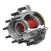
Figure 1
PreSet Plus
®
PreSet Plus
hubs feature
an integrated
spindle nut
held in place
with a retaining ring.
Disassembly
1. Remove the spindle nut system.
a. If equipped with a one-piece or multi-piece spindle nut,
follow the manufacturer or OEM guidelines for removal.
b. If equipped with a PreSet or PreSet Plus spindle nut, remove
the red locking ring from the spindle nut assembly. Use
caution not to damage the locking ring.
c. For the PreSet spindle nut, remove the spindle nut and slide
the hub o of the spindle.
d. For the PreSet Plus spindle nut, use a breaker bar to
loosen the spindle nut. Be aware that PreSet Plus spindle nut
installation torque is 300 ft-lbs for steer hubs and 500 ft-lbs for
drive and trailer hubs. After the spindle nut is initially loosened
with a breaker bar, loosen the spindle nut to remove the hub
from the spindle. The internal spiral snap ring will act as a hub
puller and will aid in removal of the hub from the spindle. Do
not exceed 50 ft-lbs of torque when removing the hub from
the spindle. If the hub will not come o without exceeding this
torque value, remove the spiral snap ring and the spindle nut
assembly and use a conventional hub puller to remove the hub
from the spindle.
e. If part of the seal remains on the spindle, carefully remove
the part of the seal that remains on the seal journal.
2. Remove the outer bearing cone from the hub assembly
being careful not to drop it.
3. Place the hub on its outboard end and remove and discard
the seal.
106804c
INNER
BEARING
CONE
SPACER
Figure 2
4. Remove the inner bearing cone and spacer from the hub
assembly (see Figure 2).
Reassembly
1. Place the hub, seal end up, on a clean work surface.
2. Visually inspect the inner bearing cup and cone for signs of
heat, wear or damage. Reference TMC RP644 for proper compo-
nent inspection procedures.
3. Lubricate the inner bearing cone with the same lubricant as
will be used in the hub and install it into the inner bearing cup
(see Figure 3).
5. R
EASSEMBLY
– P
RE
S
ET
W
HEEL
H
UBS
14 Consolidated Metco, Inc.
Reassembly
1. Place the hub, seal end up, on a clean work bench
surface.
2. For steer hubs, install the tubular bearing spacer
with the tapered end down (see figure 33).
31
Bearing Cone Assembly for Steer Hub
FIGURE 33
3. Lubricate the inner bearing cone with the same
lubricant as will be used in the hub and install it into
the inner bearing cup (see figure 34).
32
Bearing Cone Assembly for Drive Hub
FIGURE 34
4. When installing the SKF or Outrunner wheel seal,
lubricate the seal outer diameter and the hub seal
bore with the same lubricant as will be used in the
hub. The Stemco Endeavor seal is installed dry and
should not be lubricated.
5. Position the seal into the hub bore.
6. When installing the Outrunner or Stemco Endeavor
seal, tap the adapter plate of the installation tool
around the outer edge to position the seal. Drive the
wheel seal into place (see figure 35). Once the tool
bottoms out, the seal is installed correctly.
7. When installing the SKF Scotseal Plus XL, press
the seal evenly into the bore by hand (see
figure 35). If additional force is needed, use a flat
plate and a small mallet to install the seal.
When using an oil bath system, do not pack the bearing with
grease. Grease will prevent the proper circulation of axle lubricant
and can cause premature wheel seal and bearing failure.
If you are working on a drive or trailer hub, go to step 3. If you are
working on a steer hub, proceed as follows.
106810a
The seal must be replaced every time the hub is removed from the
spindle.
Do not apply any gasket sealant to the seal outer or inner
diameter.
Always use the seal installation tool specified by the seal
manufacturer. Using an improper tool can distort or damage the
seal and cause premature seal failure.
If using the Outrunner wheel seal, place the seal with the “air side”
facing the adapter plate of the installation tool.
If using the SKF Scotseal Plus XL wheel seal, no special
installation tools are required.
If using the Stemco Endeavor seal, be sure to use the Stemco
installation tool.
The Outrunner and Stemco Endeavor seals require the proper tool
for installation. Refer to the Service Parts List on page 20 of the
manual to identify the correct installation tool.
Consolidated Metco, Inc. 14Consolidated Metco, Inc. 14
Figure 3
When using an oil bath system, do not pack the bearing
with grease. Grease will prevent the proper circulation of
axle lubricant and can cause premature wheel seal and
bearing failure.
4. Ensure the hub seal bore is free of rust, dirt, scratches and
sharp edges.
Do not apply any gasket sealant to the seal outer or inner
diameter.
5. Position the seal into the hub bore with the “AIR SIDE” visible.
Use the appropriate ConMet installation plate (see chart below)
and a generic seal tool handle or a at plate and small mallet
to hammer seal into place. Do not hammer directly on the seal.
Make sure the seal is uniformly bottomed out in the bore. (see
Figure 4). Check to be certain the seal is not cocked and that
the seal inner diameter and the inner bearing turn freely.
ConMet Seal Installation Plates
Axle Type Part Number
FF Steer 10084010
FL Steer 10084011
R Drive 10084012
TN Trailer 10084013
TP Trailer 10084013
Figure 4
6. Turn the hub over, and place it seal-end down. Place the
bearing spacer in the hub cavity ensuring that the small end, if
present, faces the outboard end of the hub (see Figure 5).
5. REASSEMBLY – PRESET WHEEL HUBS (CONTINUED)
Consolidated Metco, Inc. 15
33
FIGURE 35
8. Check to be certain the seal is not cocked and that
the seal inner diameter and the inner bearing turn
freely.
9. Lubricate the inner diameter of the seal with a light
film of the same lubricant as will be used in the hub.
10. Turn the hub over, and place it seal end down. For
all drive and trailer hubs, install a bearing spacer. If
the spacer has a tapered end, it should face
towards the outboard end of the hub (see figure
36).
34
Installing the Spacer
FIGURE 36
11. Lubricate the outer bearing cone with the same
lubricant as will be used in the hub and install it into
the hub assembly (see figure 37).
35
Installing the Outer Bearing Cone
FIGURE 37
Failure to lubricate the inner diameter of the seal, and the seal
journal, may result in premature seal failure.
106811b
OUTRUNNER OR
STEMCO ENDEAVOR
SEAL
SKF SCOTSEAL PLUS XL
105748a
105749a
Consolidated Metco, Inc.15 Consolidated Metco, Inc.15
Figure 5
If during any bearing inspection there is an indication that the
existing bearing must be replaced, bearing cups and cones must be
replaced as a set. You must only replace bearings with ones approved
for use in PreSet hubs. Non-approved bearings could result in
excessive preload or endplay.