This document is an instruction manual for the Contherm CAT 1050 – 1400 Standard Incubators, manufactured by Contherm Scientific Limited. It includes a warranty statement, statement of conformity, contents, definitions of terms, introduction and specifications, operating instructions, theory of operation, customer troubleshooting and maintenance, parts lists for spares and accessories, glass door sizes, a certificate of conformance, and installation/operation quality checklists.
Function Description:
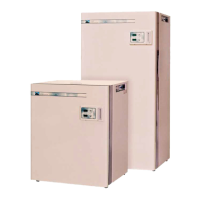
The Contherm CAT 1050 – 1400 Standard Incubators are general-purpose laboratory instruments designed to provide a controlled temperature environment for various applications. They utilize a single-chip microprocessor electronic PID controller with a 1000Ω Resistance RTD probe as the temperature sensing element. Air inside the incubator is circulated by a stirring motor, drawing air in at the top and discharging it down behind a false back to the bottom, creating a vertical airflow. A sheathed heating element is located adjacent to the air rotor, ensuring discharged air passes over the active portion of the element. An internal glass door allows viewing of contents without disturbing the internal temperature.
Important Technical Specifications:
- Temperature:
- Nominal Range: Ambient +2°C to 100.0°C
- Temporal Variation: ±0.2°C
- Spatial Variation: ±0.6°C
- Initial Overshoot: +2.0°C
- Reproducibility: ±0.4°C
- Dial Resolution: 0.1°C
- Operating Ambient: 10°C - 35°C
- Mains Voltage Range: 220-250 AC 50Hz
- Timer:
- Timing Range: 1 minute - 99 hours 59 minutes
- Timing Resolution: 1 minute
- The timer does not start timing down until within 2.5°C of the temperature SET POINT.
- Construction: High quality stainless steel interior, full fibreglass insulation, non-jar magnetic door catch, and corrosive resistant epoxy powder coated exterior.
- Safety: Fitted with an independent user-adjustable Hi-Limit, completely separate from normal controls.
- Convection: All units come with mechanical convection fan systems.
- Electrical: All quoted at 37°C - ZP21 Micro-Controller mechanical convection. Designed to AS/NZS 3350.1.1994, 220-250V AC M.E.N. Complies with EN 61326-1: 1997.
- Shelf Loading: Maximum shelf loading is 30Kg/shelf, maximum total for cabinet is 100Kg.
- Power: 220-250V Mains outlet, 10amp electrical outlet required.
- Glass Door Sizes (H x W):
- Cat.1050: 374mm x 432mm
- Cat.1100: 495mm x 507mm
- Cat.1150: 571mm x 587mm
- Cat.1200: 636mm x 700mm
- Cat.1300: 462mm x 700mm (2 doors)
- Cat.1400: 614mm x 700mm (2 doors)
- 5.0mm Toughened Clear Floated glass with all edges erased.
Usage Features:
- Installation: Install shelf runners by fitting the lug into the rear sidewall slot and clipping down into the front slot. Ensure runners are parallel. Place on a solid top with clearance underneath for ventilation (bench units). Allow at least 150mm space at the rear for air circulation. Remove all cable ties inside the cabinet before operation.
- Operating Controller:
- Plug into a 220-250V Mains outlet.
- Turn on the main switch; the LED display will show "8888s" then the current temperature. Do not press buttons until "8888s" disappears.
- To set temperature: Press and HOLD the temperature button until the 'SET' LED comes ON, then release. Use 'UP' & 'DOWN' buttons to adjust the SET POINT. Wait for the display to return to normal.
- To set timer: Use the same method as for temperature, but press the 'TIME' button. Adjust to '0.00' for OFF, or '99:59' then 'up' once for continuous operation (indicated by '[.]' symbol).
- To view current time: Press 'TIME' button for 2 seconds.
- To view current temperature: Press 'TEMP' button for 2 seconds.
- To cancel an alarm: Press and HOLD the 'TEMP' button until the 'SET' LED comes ON.
- Mechanical Hi-Limit Monitor: This is a secondary safety device. To set: Turn the Hi-Limit control FULLY CLOCKWISE. Allow the cabinet to stabilize at the required operating temperature (at least 1 hour). Turn the Hi-Limit control anti-clockwise until the MONITOR neon comes on (or a slight 'click' is felt). Then turn it SLOWLY CLOCKWISE until the MONITOR neon goes off (or a slight 'click' is felt). Advance the Hi-limit clockwise 1-2 scale markings to set the trip point about 3-4°C above the current cabinet temperature.
- Calibration:
- Place a calibrated thermometer probe in the workspace center (empty chamber).
- Set the controller for 37.0°C or the temperature of interest and allow at least 1 hour to stabilize.
- Read the temperature on the Calibration Thermometer.
- To calibrate: Press and HOLD the 'TEMP' button until the 'SET' LED comes ON. While 'SET' LED is ON, press BOTH 'UP' & 'DOWN' buttons TOGETHER. A beep will be heard, and 'CAL' will appear. Adjust the LED display to match the Calibration Thermometer using 'UP' & 'DOWN' buttons. Wait for another beep, the LED will show '----' then the CALIBRATION CONSTANT (0.0 to 19.9). Note this figure. The controller will then resume normal operation.
- Alarms: Indicated by a number and three dashes on the LED display with an audible alarm.
- 1---: Over or Under temperature. Check door, internal fan, or Hi-Limit setting.
- 3---: Preset alarm (memory failure). Reset all control settings and check calibration.
- 4---: Temperature sensing probe (1000Ω RTD) failed. Check probe connections and condition.
- 9---: WATCHDOG alarm (Electronic PCB failed). Replace controller.
- Fan Motor: May 'PULSE' when ambient temperature is close to the set point due to 'Thermoguard' mode reducing heating effect.
Maintenance Features:
- Exterior: Wipe the epoxy powder coated mild steel exterior with a damp cloth occasionally.
- Interior: Keep the stainless steel interior and shelves clean with a damp cloth. Avoid damaging the temperature probe. Clean up spills or breakages immediately with the cabinet switched off and unplugged.
- Humidity: Not suitable for high humidity conditions where water condenses on walls, floor, or inside the outer door.
- Fan Motor Bearings: Do not require lubrication under normal conditions.
- Routine Maintenance (Annually Suggested):
- Check glass door gaskets for damage (cuts and splits); replace if necessary.
- Check glass door(s) seal correctly; adjust door hinge if required for split glass doors.
- Wipe out the floor of the cabinet to remove water stains.
- Check controller overlay for damage; replace if necessary.
- Check basic cabinet control functions and that the user hi-limit control is set appropriately.
- Electrical Safety: Periodically test for insulation and earthing continuity according to AS/NZS 3760. This includes a visual check for damage, an earth continuity test, and an insulation resistance test.
- ZP21 Controller PCB Removal/Replacement: This must be carried out by suitably qualified electrical personnel. ENSURE power cord is REMOVED. Loosen plastic fasteners, lift lid. Remove self-tapping screws, rotate panel up. Unplug socket from Controller PC Board, noting connections. Undo 4mm securing nuts, noting SPACERS. Remove PC Board. Refit in reverse order, ensuring correct connections. Carry out Insulation and earth continuity checks BEFORE applying power. Check for loose wires, especially earth wires.