Do you have a question about the Continental Refrigerator Permold IOF-550-B and is the answer not in the manual?
Defines the manual's scope and purpose, covering IOF-550 series engines and related documentation.
Explains symbols used to denote specific engine model applicability within the manual.
Defines the types of advisories (WARNING, CAUTION, NOTE) used for safety and clarity.
Guides users on how to effectively utilize the manual and related publications for ICAs.
Outlines owner/operator responsibility for ensuring airworthiness and compliance with regulations.
Establishes the hierarchy of instructions for engine operation and continued airworthiness.
Lists related TCM publications and their accessibility via TCMLINK.
Details the six categories of Service Documents issued by TCM and their purpose.
Lists relevant TCM publications, supplier bulletins, and accessory documents for engine installation.
Explains how to access TCM publications via TCMLINK and authorized distributors.
Discusses how TCM delivers updated information and the role of Service Documents.
Invites user feedback and specifies how to report errors affecting safety.
Provides contact details for Teledyne Continental Motors for technical assistance and inquiries.
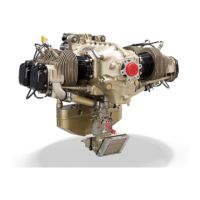
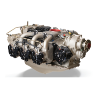
Provides an overview of the IOF-550 Permold Series engines, their configuration, and key features.
Explains the alphanumeric characters in the engine model number for identification.
Details the numbering system for engine cylinders and the firing order.
Describes specific engine components such as crankcase, drive train, cylinders, lubrication system, FADEC, etc.
Describes the construction and features of the engine crankcase, including mounting pads and ventilation.
Explains the torque transmission from the starter to various engine components via gears.
Details the crankshaft construction, counterweights, and drive gear attachment.
Describes the camshaft's construction, function in valve operation, and drive provisions.
Explains the function of the idler gear in driving accessory drive gears.
Describes the six horizontally-opposed cylinders, their cooling, head/barrel assembly, and port design.
Details the piston construction, ring grooves, and weight variation limits.
Explains the dual function of hydraulic lifters in the valve train and maintaining zero clearance.
Describes the function of the lubrication system and its key components.
Explains the positive displacement oil pump's operation, components, and pressure regulation.
Describes the construction of oil sumps for different models and their features like drain plugs and connectors.
Explains the operation of the oil cooler and the vernatherm valve in regulating oil temperature.
Introduces the FADEC system, its role, and components like ECUs and sensors.
Details the structure and function of the three ECUs controlling fuel mixture and ignition timing.
Explains the function of the low voltage harness connecting FADEC system components.
Describes the high voltage harness connecting ECUs to spark plugs for ignition.
Details the integration of the boost pump mode switch with the FADEC system.
Explains the pilot's selection of Best Power or Best Economy modes via a switch.
Describes the Speed Sensor Array's role in providing crank position and speed to the FADEC.
Explains the function and mounting of CHT Sensors for monitoring cylinder head temperature.
Details the EGT Sensors' role in reporting temperature for fuel-to-air ratio control.
Describes the MAP Sensors' function in measuring induction air pressure for the FADEC system.
Explains the MAT Sensors' function in measuring intake manifold air temperature.
Details the function of the two fuel pressure sensors in measuring available fuel pressure.
Outlines various options for engine control indications in the crew compartment displays.
Describes the two-lamp HSA panel and its warning/caution indicators for system malfunctions.
Describes the optional engine control panel (ECP) with diagnostic features and message display.
Details the optional Engine Data Interface (EDI) for crew compartment data storage and display.
Describes the engine-driven fuel pump, distribution block, throttle body, and injector assemblies.
Explains the fuel pump's positive displacement operation, capacity, and aneroid valve function.
Details how ECUs meter fuel to cylinders via solenoid-actuated sequential port fuel injectors.
Explains the electric starter motor's operation via a right-angle drive adapter and clutch assembly.
Describes the gear-driven or belt-driven alternator's function in generating electrical current.
Explains how engine cylinders are cooled by airflow directed by cowling, baffles, and cowl flaps.
Describes the induction system's role in carrying air to cylinder intake ports for fuel mixing.
States the exhaust system is provided by the customer.
Refers to tables for model-specific specifications and operating limits.
Lists general, crankshaft, fuel system, ignition, and fuel consumption specs for IOF-550-B.
Lists general, crankshaft, fuel system, ignition, and fuel consumption specs for IOF-550-C.
Lists specs for IOF-550-N, P, and R models, covering general, crankshaft, fuel, and ignition.
Lists drive ratios, rotation, speed, torque, and overhang moments for engine accessories.
Describes the AND20000 specification for the accessory drive pad, including its modification and cover.
Lists recommended oil grades and types for Teledyne Continental Motors engines.
Specifies the SAEJ1966 standard for break-in mineral oil and its usage limitations.
Lists lubricating oils qualified under SAEJ1899 or SAEJ1966 for TCM engines.
Refers to TCM Detailed Model Specifications for complete engine technical data and test performance.
Lists special tools for reference, not as endorsements, and notes alternative sources.
Lists special tools for reference, not as endorsements, and notes alternative sources.
Provides contact details for suppliers of tools, accessories, and supplies.
Lists special tools with corresponding figures for visual identification and reference.
Lists common tools required for performing engine overhaul procedures.
Provides information on qualified lubricants, sealants, and adhesives for engine use.
Specifies recommended intervals for engine oil and filter changes based on hours or months.
Discusses the compatibility and recommended use of fuel and oil additives in aircraft engines.
States that components with mandatory replacement times are not included by type certification.
Notes that specific inspection intervals are not required by type certification, subject to ADs.
States no other related procedures are required by type certification, subject to ADs.
Explains that changes require FAA approval and are published in FAA Airworthiness Directives.
Refers to other manuals for abbreviated and detailed engine removal and installation procedures.
Outlines operational checks to perform after engine installation, maintenance, or overhaul.
Details the preflight inspection steps to ensure the aircraft and engine are airworthy before starting.
Describes procedures for verifying engine operation using FADEC diagnostics or calibrated gauges.
Lists required equipment and procedures for checking engine operation using FADEC diagnostics software.
Provides procedure for checking engine operation using calibrated gauges, focusing on fuel system pressures.
Details the step-by-step procedure for performing an operational check using the Health Status Annunciator (HSA).
Outlines the procedure for performing an operational check using the Engine Control Panel (ECP).
Instructs users to make a copy of the checklist to record operational test results.
Introduces the inspection program applicable to TCM engines and refers to related sections.
Presents the engine inspection and maintenance schedule applicable to TCM engines.
Describes scheduled inspections performed at predetermined intervals to maintain physical integrity.
Details how to check and adjust the tension of new drive belts after initial operation.
Specifies the frequency and tasks for the initial operation inspection after engine service or component replacement.
Outlines the circumstances and procedures for performing the 50-hour engine inspection.
Details the frequency and procedures for the 100-hour or annual engine inspection.
Specifies the procedure for the 500-hour engine inspection.
Outlines the procedure for inspecting the alternator, including drive hub slippage.
Provides general visual inspection procedures for the engine and its components.
Details the comprehensive inspection of engine cylinders, including various checks and references.
Guides on visually inspecting cylinder barrel and fins for cracks, damage, and pitting.
Explains the purpose, frequency, and procedure for testing cylinder differential pressure.
Provides procedure to establish acceptable pressure leakage limit for the E2M tester with Master Orifice Tool.
Details the procedure to establish acceptable leakage limit for the E2A tester with Master Orifice Tool.
Outlines steps to keep the differential pressure tester clean and periodically check its accuracy.
Provides a step-by-step procedure for conducting the cylinder differential pressure test.
Explains how to check static seals for leakage by listening for air flow at ports and staking valves.
Describes the visual inspection of internal cylinder components using a borescope without disassembly.
Details inspecting the cylinder mounting deck for sealant and ensuring proper torque.
Explains the importance of verifying baffle installation, integrity, and positioning for cylinder cooling.
Checks cowl openings for restrictions and proper operation of cowl flaps.
Outlines procedures to verify crankcase integrity, fastener torque, and absence of leaks or damage.
Details inspecting engine mounts and isolators for cracks, deterioration, and security.
Covers checking the air filter, seals, and airbox integrity to prevent engine damage.
Guides on verifying FADEC components, ignition leads, and spark plug condition.
Specifies conditions for replacing the FADEC system backup battery.
Outlines verification of fuel injector operation, filter cleaning, and fuel pump calibration.
Details cleaning the fuel distribution block filter for 100-hour inspections.
Provides step-by-step instructions for servicing the fuel distribution block filter on B & C models.
Outlines the procedure for cleaning and inspecting the bypass fuel filter assembly for N, P, and R models.
Explains how to service bypass fuel filter assemblies at 100-hour intervals.
Guides on verifying the proper operation of engine gauges and ensuring reliable feedback to the pilot.
Details inspecting engine control linkage rods for excessive play to prevent wear and breakage.
Explains how to check fuel system drains to prevent fuel accumulation and fire hazards.
Outlines the procedure for inspecting the alternator, including checking for wear and proper installation.
Describes the inspection of the alternator coupling's elastomeric element for shearing or tearing.
Details the procedure for testing ground strap continuity to ensure proper FADEC system grounding.
Covers maintenance tasks performed due to specific events like propeller strikes or hydraulic lock.
Defines a propeller strike and its potential for engine damage and catastrophic failure.
Outlines the inspection procedure after a propeller strike or when propeller removal is necessary.
Describes hydraulic lock conditions, causes, and potential engine damage.
Explains engine overspeed conditions, severity levels, and potential damage.
Details the procedure for inspecting the engine after a Category I overspeed condition.
Outlines inspection and replacement requirements after a Category II overspeed condition.
Refers to evaluation by a service representative for excessive overspeed cases.
States that lightning damage assessment requires internal inspection.
Provides procedures for handling contaminated fuel systems, including draining and cleaning.
Refers to another section for information on abnormal ferrous material in oil analysis.
Recommends lifter and camshaft lobe inspection if abnormal noise is detected.
Explains the purpose of inspection checklists for recording progress and findings.
Introduces troubleshooting charts, probable causes, and corrective actions for engine anomalies.
Provides general guidelines to expedite diagnosis of engine anomalies.
Details troubleshooting steps for engines running rough at idle or high speed.
Outlines troubleshooting steps for when the engine fails to run at idle.
Addresses troubleshooting abnormal engine indications from fuel, FADEC, or lubrication systems.
Guides troubleshooting for poor engine performance at full throttle or with air filter issues.
Covers troubleshooting for induction system issues like engine not starting or lacking power.
Provides troubleshooting steps for when the engine fails to start, focusing on induction system.
Outlines troubleshooting steps for when the engine will not run at idle speed, focusing on induction system.
Details troubleshooting steps for reduced engine power or manifold pressure.
Addresses troubleshooting for fuel injection system issues, including fluctuating or erroneous fuel flow indications.
Guides on performing a visual inspection and check of the fuel injection system's operational status.
Refers to airframe manufacturer's information for charging system troubleshooting.
Covers troubleshooting for FADEC system components, diagnostics, and sensors.
Details the requirements and methods for performing FADEC Level I diagnostics.
Provides a flowchart for isolating FADEC power-on faults without an Engine Data Interface.
Outlines fault isolation for FADEC power-on issues using the Engine Data Interface.
Guides troubleshooting by visualizing the FADEC system as four major sub-systems.
Describes ECU removal and installation procedures, emphasizing no field serviceable parts.
Details the removal and installation of the Engine Data Interface (EDI).
Provides troubleshooting steps for the Speed Sensor Assembly (SSA), including checking wiring and connectors.
Details the removal and installation of MAP sensors, noting they are not field serviceable.
Explains the removal and installation of fuel pressure sensors, noting they are non-serviceable.
Describes the removal and installation of MAT sensors, noting they are hard-wired.
Details the removal and installation of CHT sensors, emphasizing correct cylinder placement.
Explains the removal and installation of EGT sensors, noting their designation by cylinder.
Provides troubleshooting steps for starter motor issues like not turning or turning slowly.
Addresses troubleshooting for ignition system issues such as excessive RPM drop or rough running.
Details troubleshooting steps when the engine fails to start, focusing on ignition system.
Outlines troubleshooting steps for engines running rough, focusing on ignition harness and spark plugs.
Provides troubleshooting steps for when the engine will not stop, focusing on ignition switch operation.
Guides on diagnosing ignition harness and spark plug issues for abnormal RPM or performance drop.
Covers troubleshooting for oil temperature and pressure malfunctions.
Details troubleshooting steps for high oil temperature indications.
Outlines troubleshooting steps for low oil pressure indications.
Lists inspection details for cylinders, including bore, differential pressure, and borescope checks.
Guides troubleshooting for rough idling conditions, including cylinder differential pressure checks.
Details troubleshooting steps for high cylinder head temperature indications.
Addresses troubleshooting for crankcase issues like oil leakage or excessive pressure.
Provides troubleshooting steps for excessive crankcase pressure, including checks of the air/oil separator and breather system.
Covers troubleshooting for loose crankcase accessories and mounting hardware.
States the exhaust system is an airframe component and refers to airframe manufacturer procedures.
Outlines procedures to check cabin harness functionality for FADEC System components.
Details the electrical ground check procedure using a DVM for connector pin layouts.
Guides on checking the resistance of enable switches for different ignition switch positions using a DVM.
Details checking power supply voltages at specified pins using a DVM for FADEC system components.
Outlines the procedure for checking the boost pump relay in a well-ventilated area.
Provides schematics to aid in FADEC troubleshooting, noting differences between engine models.
Presents wiring diagrams for the FADEC ECUs #1, #2, and #3 for IOF-550-B and C models.
Provides wiring diagrams for FADEC ECUs #1, #2, and #3 for IOF-550-N, P, and R models.
Provides cleaning guidelines for various aircraft engine parts using specified solvents.
Explains the importance of cleaning ground strap connection points for FADEC system integrity.
Provides detailed procedures for degreasing and cleaning aluminum alloy parts, including carbon/gum deposit removal.
Lists protective or anti-corrosive coatings such as Alodine, primer, enamel paint, and engine oil.
Describes applying alodine as a protective coating for aluminum surfaces after cleaning or machining.
Explains applying clean 50-weight aviation oil to cleaned steel surfaces, avoiding painted or alodined surfaces.
Details procedures for applying paint to external aluminum, ferrous, and magnesium parts.
Discusses normal oil consumption and procedures for addressing excessive consumption.
Provides procedure for checking and adding oil to maintain the specified level.
Outlines the procedure for performing an oil change, including oil sample collection and filter inspection.
Provides instructions for checking engine nacelle, compartment, and adjacent areas for oil leaks.
Explains spectrographic oil analysis for identifying internal engine problems and monitoring wear trends.
Details the times and procedures for collecting oil samples for analysis.
Covers spark plug replacement and ignition harness maintenance procedures.
Outlines the procedure for removing, inspecting, cleaning, and replacing spark plugs.
Details procedures for maintaining the high voltage harness, including lead inspection and replacement.
Specifies conditions for replacing the FADEC system backup battery.
Guides on inspecting and maintaining throttle control linkage rods for proper operation and wear.
Lists adjustment procedures including oil pressure, fuel pressure, idle speed, and belt tension.
Details the procedure for adjusting engine oil pressure at full power RPM.
Guides on adjusting fuel system settings like idle speed, full throttle, and fuel pump pressure.
Covers checking and adjusting drive belt tension for optional compressors or alternators.
Details checking and adjusting drive belt tension for the Freon compressor.
Outlines procedures for checking and adjusting alternator drive belt tension.
Refers to tables indicating repairable items and procedural references for non-overhaul replacement.
Covers fuel pump removal and installation procedures, including warnings.
Details the procedure for disconnecting engine power and removing the fuel pump.
Outlines the procedure for installing the fuel pump, including applying gasket maker and torqueing.
Details procedures for replacing the starter motor and adapter, including service limits.
Provides steps for disconnecting power, battery, and removing the starter motor assembly.
Guides on removing the starter motor and then the starter adapter assembly from the crankcase.
Details the procedure for installing the starter adapter, including cleaning, gasket application, and lubrication.
Provides steps for installing the starter motor, including O-ring, grease, torque, and electrical connections.
Covers replacing the alternator if it fails to deliver correct voltage and amperage.
Details procedures for disconnecting power and removing the direct drive alternator.
Guides on removing the alternator drive hub assembly from the alternator shaft.
Details the procedure for installing the alternator drive hub assembly, including warnings about shipping washer.
Outlines the procedure for installing the direct drive alternator, including checks and connections.
Details removing the belt-driven alternator, including belt tension release and accessory wiring.
Guides on removing the alternator bracket from the crankcase.
Covers removing the sheave adapters and sheave from the propeller shaft for belt-driven alternators.
Details installing the drive sheave and adapters onto the propeller flange.
Provides steps for installing the alternator bracket onto the crankcase and securing it.
Guides on installing the belt-driven alternator, including aligning mounting holes and securing the brace.
Covers repairing lead wires and replacing sensors in the low voltage harness.
Details the procedure for replacing EGT sensors and their lead wires, including splicing.
Outlines procedures for replacing non-EGT sensors and their lead wires, including stripping and splicing.
Warns against field repair of connectors, recommending return to TCM or authorized station.
Covers removal and installation of FADEC components like ECUs, SSA, and sensors.
Guides on installing ECU and SSA connectors, including EMI gasket and seal placement.
Details the procedure for disconnecting power and removing ground straps from ECUs and airframe.
Guides on cleaning contact surfaces, installing new ground straps, and checking continuity.
Provides steps for disconnecting power, removing harness, and extracting the ECU.
Details installing the ECU, emphasizing correct location and grounding, and connector handling.
Guides on removing the signal conditioner, emphasizing grounding and connector handling precautions.
Details installing the signal conditioner, including cleaning sealing surfaces and routing leads.
Provides a procedure to check Speed Sensor Assembly (SSA) functionality using a FADEC Timing Tool.
Outlines the procedure for checking SSA functionality using a FADEC Timing Tool and engine operational check.
Details the procedure for removing fuel injectors, emphasizing avoiding contamination.
Guides on installing fuel injectors, including flushing fuel lines and inspecting threads.
Details installing the fuel injector solenoid coil onto the injector body and securing it.
Covers removing MAP sensors, noting they are not field serviceable.
Details installing MAP sensors, including cleaning threads and checking resistance.
Outlines the procedure for removing fuel pressure sensors from the fuel distribution block.
Guides on installing fuel pressure sensors, including cleaning, thread sealing, and checking resistance.
Covers removing MAT sensors, noting they are integral to the low voltage harness.
Details installing MAT sensors, including marking body position and torquing fittings.
Outlines removing EGT sensors, including cutting lead wires and loosening band clamps.
Guides on installing EGT sensors, including routing wires and torqueing clamps.
Details removing faulty CHT sensors, including disconnecting connectors and cutting leads.
Guides on installing CHT sensors, including preparing wires and using bayonet adapters.
Outlines removing the two-lamp HSA driver from the airframe per manufacturer's instructions.
Details installing the HSA driver and lamp driver, and performing FADEC diagnostics.
Guides on removing the HSA with battery monitor, including disconnecting connectors and screws.
Outlines installing the HSA with battery monitor, securing wiring, and performing FADEC diagnostics.
Specifies conditions for backup battery replacement and refers to aircraft manuals for instructions.
Refers to applicable aircraft maintenance manual for EDI location and installation instructions.
Refers to applicable aircraft maintenance manual for ECP location and installation instructions.
Details repair procedures for lubrication system components like oil pumps and coolers.
Outlines replacing the oil filter adapter stud, including cleaning threads and applying sealant.
Details repairing or replacing oil pumps or tach drive components, referencing service limits.
Covers replacing the oil sump and oil suction tube, referring to overhaul manual instructions.
Guides on repairing or replacing the oil cooler, noting that structural repairs are not allowed.
Details inspecting and replacing the oil pressure relief valve, including plunger and seat.
Describes using a spot facer tool to reface the valve seat if it is nicked or rough.
Guides on inspecting and replacing the oil temperature control valve, including applying anti-seize.
Covers procedures for replacing or servicing individual engine cylinders, not overhaul.
Details removing the valve train and pushrods from IOF-550-B & C cylinders.
Provides steps for removing cylinders from IOF-550-B & C engines, including component inspection.
Details removing the valve train and pushrods from IOF-550-N, P, & R cylinders.
Guides on removing cylinders from IOF-550-N, P, and R engines, including component inspection.
Refers to appropriate sections for dimensional limits of IOF-550-B/C and IOF-550-N/P/R engines.
Lists service limits for cylinder assembly, rocker arms, and pistons for B & C models.
Provides service limits for cylinder assembly, rocker arms, and pistons for N, P, and R models.
Guides on installing engine cylinders, verifying component tolerances and proper assembly.
Details the installation of IOF-550-B & C engine cylinders, including O-ring, valve train, and torque procedures.
Outlines the installation of IOF-550-N, P, and R engine cylinders, including cleaning and lubrication.
Provides instructions for installing drain tube fittings and drain valves on IOF-550-N, P, & R cylinders.
Details the torque sequence for single cylinder installation and through bolts.
Guides on removing hydraulic tappets and inspecting them for wear or damage.
Details installing hydraulic valve tappets and pushrod assemblies, including lubrication.
Provides steps for installing valve mechanism parts and pushrods on IOF-550-B & C cylinders.
Details installing valve mechanism parts and pushrods on IOF-550-N, P, & R cylinders, including side clearance checks.
Addresses repairing crankcase cracks and correcting leaks, with warnings on serviceability.
Outlines criteria for applying repair and replacement procedures to crankcases.
States that only FAA-approved facilities can perform crankcase weld repairs.
Instructs to replace leaking crankcase gaskets.
Details replacing camshaft plugs, emphasizing proper installation to avoid oil pressure loss.
Specifies conditions requiring replacement of the crankshaft nose oil seal.
Guides on removing the crankshaft nose oil seal, including precautions and cleaning procedures.
Details the installation of the crankshaft nose oil seal, including cleaning, spring placement, and lubrication.
Details maintenance for optional air conditioning system components like compressor alignment and belt tension.
Guides on checking compressor, starter adapter, and idler sheave alignment using a pulley alignment tool.
Details installing and adjusting the compressor drive belt tension using a tension gauge or deflection method.
Refers to instructions in the Installation and Operation Manual for engine preservation.
Lists and defines acronyms used throughout the publication.
Provides definitions for terms used in the manual.
Provides general information on torque values for hardware on TCM aircraft engines.
Offers tips on checking hardware, verifying size, ensuring wrench accuracy, and aligning cotter pin holes.
Details the multi-stage torquing procedure for cylinder installation, including lubrication.
Explains how to determine appropriate torque wrench settings when using extensions.
Provides precautions, warnings, and tips for safely handling engine parts during removal and installation.
Discusses the importance of using quality parts and compliance with FARs for aircraft safety.
Discusses the importance of quality and origin of replacement parts for aircraft safety.
Explains TCM's ICAs and FAA regulations regarding approved parts.
Advises caution when using reproduced parts from unknown sources due to potential quality issues.
Mandates replacement of specific components during engine overhaul as per service bulletins.
Lists parts that must be discarded and replaced with new ones during engine overhaul.
Explains the use of oversize/undersize parts and their mating requirements.
Refers to Appendix B for torque specifications for hardware using calibrated torque wrenches.
Details procedures for securing hardware using safety wire to prevent loosening.
Explains how to install tab washers correctly to ensure hardware security.
Covers the removal and installation of helical coil inserts in tapped holes.
Details the procedure for extracting helical coil inserts using a proper size tool.
Guides on inserting helical coil inserts into tapped holes, including wall thickness checks.
Details procedures for removing and installing studs, including different types and oversize options.
Guides on removing studs using an extractor tool or drilling.
Outlines procedures for installing studs, including cleaning holes and selecting correct size.
Details precautions and procedures for removing size-on-size Rosan studs to prevent cylinder damage.
Describes two methods for removing step-type Rosan studs using special tools or machining.
Outlines the first method for removing step-type Rosan studs using a special tool.
Details the second method for removing step-type Rosan studs using machining.
Guides on installing Rosan studs (size-on-size or step type) to specified dimensions.
Provides instructions for correctly installing cotter pins to secure hardware, emphasizing replacement of used pins.
Guides on applying Gasket Maker sealant correctly, including surface preparation and torqueing.
Outlines procedures for installing new gaskets correctly and torquing hardware to prevent oil loss.
Details proper installation of hoses and tubing to fittings, emphasizing torque and support.
Provides guidelines for routing harnesses to prevent chafing, vibration, and heat exposure.
| Brand | Continental Refrigerator |
|---|---|
| Model | Permold IOF-550-B |
| Category | Engine |
| Language | English |