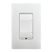
Wireless Switch
Installation Guide
Supported Models and Requirements
• C4-SW1-ZWirelessSwitch(802.15.4),White
Specications and Supported Fixtures
ThisControl4
®
WirelessSwitchoperatesindependentlyoraspartofaControl4®home
automationsystemtoenableintelligentlightingcontrol.Itinstallsinastandardwallbox
usingtypicalwiringstandardsandcommunicateswithotherdevicesthroughawireless
RF(radiofrequency)connection.Thespecicationsandsupportedxturesaredescribed
next.
Power:
120VAC+/-10%50/60Hz
300mWoff
400mWon
Supported Load Types
and Ratings:
120VAC1000WResistive
120VAC500WTungsten
120VAC1000WElectronicLowVoltage
120VAC1000WMagneticLowVoltage
ThisdevicerequiresaneutralAC
connection.
Operating Temperature:
Allloadratingsarebasedonanambient
temperatureof25degreesCelsius.
Volume:
5.0Cubicinches
Communications:
ZigBee,IEEE802.15.4,2.4GHz,
15-channel,spreadspectrumradio
Warnings and Considerations
WARNING! Installinaccordancewithallnationalandlocalelectricalcodes.
WARNING! ImproperuseorinstallationcancauseSERIOUSINJURY,
DEATHorLOSS/DAMAGEOFPROPERTY.
WARNING!Ifyouareunsureaboutanypartoftheseinstructions,consulta
qualiedelectrician.
WARNING!Usethisdeviceonlywithcopperorcoppercladwire.Thisprod-
ucthasNOTbeenapprovedforusewithAluminumwiring.
IMPORTANT!Usingthisproductinamannerotherthanoutlinedinthis
documentvoidsyourwarranty.Further,Control4isNOTliableforany
damageincurredwiththemisuseofthisproduct.See“Limited2-Year
Warranty.”
IMPORTANT! Therangeandperformanceofthewirelesscontrolsystemis
highlydependentonthefollowing:(1)distancebetweendevices;(2)layoutof
thehome;(3)wallsseparatingdevices;and(4)electricalequipmentlocated
neardevices.
Installation Instructions
TURNOFFPOWERbyswitchingoffthecircuitbreakerorremoving
thefuseandtestthatpowerisoffbeforewiring!
Identifyyourwiringapplication(refertotheappropriatediagramon
thenextpage).
• Single-Pole(withpowersourceatwallbox)-seeFigure1
• 3-Way(withpowersourceatwallbox)-seeFigure2
1.
2.
6.
IfyouareusingtheControl4push-on(screw-less)wallplatethatshippedwithyour
switch:
Sample Wiring Congurations
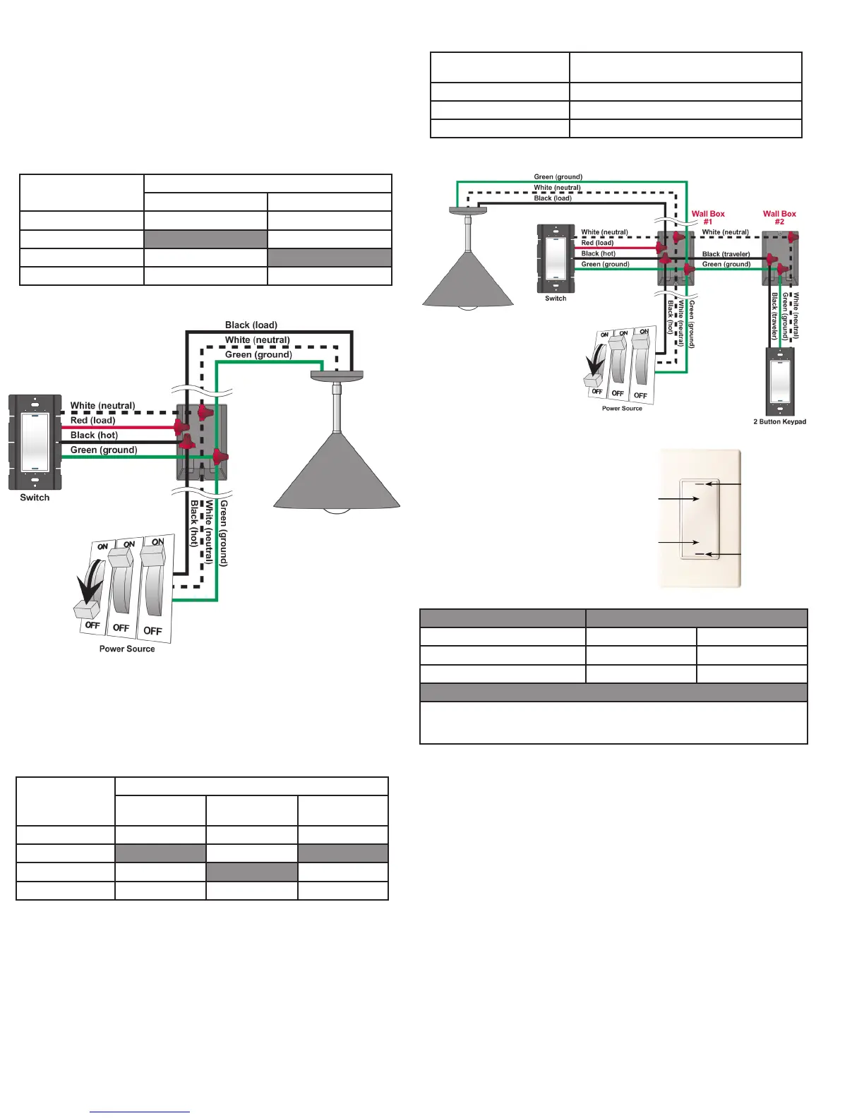
Single-LocationScenario—PowerSourceatWallBox
Note:ThisdevicewillnotfunctionwithoutaneutralACconnection.
TowiretheSwitchforaControl4single-locationscenarioinwhichthepowerisrstrouted
tothewallbox,connecttogetherandcapwithawirenutthewiresindicatedinthe
followingtableandgure:
Switch Wires Wires in the Wall Box
From Power Source To Light Fixture
White(neutral) White(neutral) White(neutral)
Red(load) None Black(load)
Black(hot) Black(hot) None
Green(ground) Green(ground) Green(ground)
Two-LocationScenario—PowerSourceatWallBox
Note:ThisdevicewillnotfunctionwithoutaneutralACconnection.
TowiretheSwitchandamulti-buttonkeypadinatwo-locationscenario(Control4’s3-way-
Switchsolution)wherethepowerisrstroutedtothewallbox,dothefollowing:
Switch Wires Wires in Wall Box 1
From Power
Source
To Light Fixture To Wall Box 2
White(neutral) White(neutral) White(neutral) White(neutral)
Red(load) None Black(load) None
Black(hot) Black(hot) None Black(traveler)
Green(ground) Green(ground) Green(ground) Green(ground)
Multi-Button Keypad Wires Wires in Wall Box 2
(from Wall Box 1)
White(neutral) White(neutral)
Green(ground) Green(ground)
Black(traveler) Black(traveler)
Preparethewiresbyremovingpre-cut
insulationfromtheappropriateswitchleads.
Wireinsulationshouldbestrippedback5/8of
aninchfromthewireend(asshown).
ConnecttheSwitchwirestothewallboxwires
usingwirenutsaccordingtotherelevant
wiringdiagram.
MounttheSwitchintothewallboxbypartially
securingthewallboxscrewsattachedtothe
Switch.Ensurethattheword“Top”onthe
Switchframeisfacingup.Bendthewiresina
zigzagpatternsothattheyeasilyfoldintothe
wallbox.
3.
4.
5.
WARNING!GroundtheWirelessSwitchinaccordancewiththeNational
ElectricCode(NEC)requirements.Althoughtheswitch’saluminumyokeplate
andgreengroundwirearedirectlybondedtogetherinsidetheSwitch,
DONOTrelysolelyupontheyokeplate’scontactwithametalwallboxfor
adequategrounding.UsetheSwitch’sgroundwiretomakeasecure
connectiontothesafetygroundoftheelectricalsystem.
7. IfyouareusingDecora-style,screw-onthewallplate:
Figure 1. Wiring: Power Source at Wall Box
1. WiretheSwitchintoWallBox#1byconnectingandcappingthewireswithawire
nutasindicatedinthefollowingtableandgure:
2. Wirethemulti-buttonkeypadintoWallBox#2byconnectingtogetherandcapping
thewireswithawirenutasindicatedinthefollowingtable:
Figure 2. Wiring: Two-Location Scenario
Operation and Conguration
Operate Switch Expected Behavior of RGB LEDs:
To operate switch: Top Bottom
TurnON:Taptop. Lit,fullbrightness Notlit
TurnOFF:Tapbottom. Notlit Lit,fullbrightness
Care and Cleaning
DoNOTpaintswitchoritswallplate.
DoNOTuseanychemicalcleanerstocleantheswitch.
Cleansurfacewithasoftdampclothasneeded.
Oninitialpowerup,theunitwillashthe
Red/Green/Blue(RGB)LEDs,whichcan
beprogrammedwithdifferentcolorsfor
differentstatesorcolorpreferences.To
setupthisSwitchforusewithaControl4
system,refertoyourComposer Pro User
Guide.
TooperatethisSwitchasastand-alone
device,refertothefollowingtable:
Troubleshooting
Iflightdoesnotturnon:
• EnsureatleastoneLEDislit.
• Ensurethelightbulbisnotburnedoutandisscrewedintightly.
• EnsurethatthecircuitbreakerisnotturnedOFFortripped.
• Checkforproperwiring(see“SampleWiringCongurations”).
• Forhelpontheinstallationoroperationofthisproduct,emailorcalltheControl4
TechnicalSupportCenter.Pleaseprovideyourexactmodelnumber.
Contactsupport@control4.comorseethewebsitewww.control4.com.
IMPORTANT!Notgroundingthisproductaccordingtotheprecedingmay
resultinaninstallationlessimmunetodamagecausedbyelectrical
disturbances,suchaslightning,andvoidthewarranty.
c. Withthewallplate’sremovalslotfacingdown,pushthewallplateonto
theswitch’sblackplasticsub-plate.
a. Forasingle-gangscenario,attachtheblackplasticsub-plateusingtheprovided
sub-platescrews.
IMPORTANT!Tightenthescrewsuntilthebacksideofthemetalyokeplate
isevenwiththewallsurface,butnofarther.Over-tighteningcandamagethe
Switchandcausemechanicalmalfunction.DoNOTuseapowerscrewdriver
toinstallthisdeviceasthismayleadtoover-tightening.
b. Ifyouareinstallinginamulti-gangscenario,onlypartiallytightenthemounting
screws,leavingabout1/8ofaninchgapbetweenthewallandtheyokeplates
priortoattachingtheblackplasticsub-plate.Thisallowseachdeviceinamulti-
gangscenariotoconformtothesub-plate,creatingasingleassembly.Secure
themulti-gangsub-platetoalldevicesusingtheprovidedsub-platescrews.Then
securetheassemblybytighteningthewallboxscrewstheremaining1/8ofan
inch.Donotover-tightenanyofthescrewsoryouwillmis-aligntheatplaneof
themulti-gangwallplate.
8.
9.
TurnONpoweratthecircuitbreakerorreplacethefusefromthefuse
box.
TesttheSwitchtoseeifit’sworkingproperly.See“Operationand
Conguration”forspecicinstructions.
a.
b.
c.
DonotattachtheSwitch’sblackplasticsub-plate.
Aligntheswitchtothewallboxandfastenitwithscrews.
FastenthewallplatetotheSwitchwithscrews.
Tap Top
(Raised)
Bottom RGB LED
Removal Slot
Top RGB LED
Tap Bottom
(Concave)

 Loading...