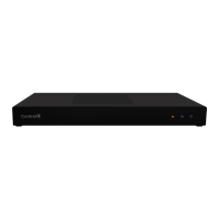
Front view
A Data LED —The Data LED turns red when an over-current condition
on the contact outputs is detected.
B Status LED —The Status LED flashes blue during the boot process
Note: The Status LED flashes orange during the factory restore
process. See “
Resetting to factory settings
” in this document.
C Link LED —The blue LED indicates that the IO Extender has been
identified in the project and is communicating with Director.
D Power LED —The blue LED indicates that power is connected. The
IO Extender turns on immediately after power is applied to it.
Back view
A Power plug port —AC power receptacle for an IEC 60320-C13 power
cord.
B SERIAL — Four DB9 serial ports for RS-232 control. See “
Connecting
the serial ports
” in this document.
C ID—ID button to identify the device in Composer Pro.
D IR—Eight 3.5 mm jacks for up to eight IR emitters. See “
Setting up IR
emitters
” in this document for more information.
E ETHERNET — RJ-45 jack for a 10/100BaseT Ethernet connection. The
IO Extender can be powered over Ethernet with a PoE+ connection.
F LEDs — Rear LEDs that mirror the status of the LEDs on the front.
G FACTORY RESET —Factory reset button to restore the IO Extender to
factory defaults. See “
Resetting to factory settings
”
H Contact/Relay port —Connect up to eight relay devices and eight
contact sensor devices to the terminal block connector. Relay
connections are COM, NC (normally closed), and NO (normally
open). Contact sensor connections are +12, SIG (signal), and GND
(ground).
Installing the IO Extender
To install the IO Extender:
1 Ensure that the home network is in place before starting system
setup. The IO Extender requires a network connection to use all of
the features as designed.
2 Mount the extender in a rack or stacked on a shelf. Always allow
plenty of ventilation. See “
Mounting the IO Extender in a rack
” in
this document.
3 Connect system devices. Attach IR, serial, contact, and relay
devices as described in “
Connecting the serial ports,
” “
Connecting
the contact ports
,” “
Connecting the relay ports
,” and “
Setting up
IR emitters
.”
4 Connect the controller to the network. Connect an Ethernet patch
cable to the RJ-45 port and to the network port on the wall or at
the network switch.
Note: If powering the IO Extender with a PoE+ connection, we
recommend that you connect any external devices (serial, IR,
contacts, and relays) first, before powering up the IO Extender
with the Ethernet PoE connection.
A B C D
A B C D E F G H
Control4 IO Extender V2
Installation Guide
Supported model
• C4-IOXV2 Control4® IO Extender V2
Introduction
The Control4® IO Extender V2 enables a Control4 system to control
home theaters, video devices, garage doors, motion sensors, and other
devices that use infrared (IR), serial, contact, and relay connections.
The IO Extender serves well as the companion to the EA Series of
entertainment and automation controllers to expand input and output
capabilities of a Control4 system.
The IO Extender V2 adds the ability to power the device by PoE+ to
simplify installation and provide power and network connectivity over a
single CAT5e/CAT6 network cable.
In addition, the IO Extender V2 provides flexible options for mounting
in an equipment rack (1U) or on a shelf. The included rack ears may
be installed at the front or back of the IO Extender V2 for maximum
installation flexibility.
Box contents
The following items are included in the box:
• IO Extender V2 (C4-IOXV2)
• AC power cord
• IR emitters (8)
• Warranty card
• Rack ears (2)
• Four-position terminal blocks for contacts and relays (4)
Accessories sold separately
• Control4 Gigabit PoE+ Injector (AC-POE2-B)
• Pakedge Managed Gigabit Switch with 8 Rear Facing PoE+/PoE
Ports (SX-8P)
• Pakedge 24 Port Managed Switch with 24 PoE or 12 PoE+ Ports
(SX-24P)
Warnings
Caution! To reduce the risk of electrical shock, do not expose
this apparatus to rain or moisture.
Avertissement ! Pour réduire le risque de choc électrique,
n’exposez pas cet appareil à la pluie ou à l’humidité.
Caution! In an over-current condition on contact output the
software disables the output.
If the attached contact sensor
does not appear to power on, remove the device from the
controller.
Avertissement ! Dans une condition de surintensité sur sortie
de contact le logiciel désactive sortie. Si le capteur de contact
connecté ne semble pas s’allumer, retirez le périphérique du
contrôleur.
Requirements and specifications
Note: The Ethernet network should be installed before you
install the IO Extender.
• Composer Pro is required to configure this device. See the
Composer
Pro User Guide (
ctrl4.co/cpro-ug
) for details.
• The IO Extender V2 requires Control4 OS 2.9 or newer.
Specifications
Model number
C4-IOXV2
Network
Ethernet
10/100BaseT compatible
Inputs / Outputs
IR OUT
8 IR out—5V 27mA max output
SERIAL OUT
4 DB9 ports
Contact
8 contact sensors—30VDC maximum input
12VDC 1.25A maximum output
Relay
8 relays—AC: 36V, 2A; DC: 24V, 2A maximum
Power
Power requirements
100-240 VAC, 60/50 Hz or
PoE+—up to 25.5W, IEEE 802.3at-2009
Power consumption
Max: 30W, 102 BTUs/hour
Idle: 10W, 34 BTUs/hour
Other
Operating temperature
32˚ ~ 104˚F (0˚ ~ 40˚C)
Storage temperature
4˚ ~ 158˚F (-20˚ ~ 70˚C)
Dimensions (H x W x D)
17.5" (444 mm) x 10.125" (258 mm) x 1.875"
(49 mm) w/feet
Mounting
1U rack mount with included rack ears
Weight
6.55 lbs (2.97 kg)
Shipping weight
9.60 lbs (4.35 kg)
Additional resources
The following resources are available for more support:
• Control4 Knowledgebase (
kb.control4.com)
and Dealer Forums
(
forums.control4.com)
• Control4 Technical Support
• Control4 website (
www.control4.com)
• Composer Pro documentation in online help or PDF format available
on the Dealer Portal under Resources (
ctrl4.co/docs)
5 Power up the IO Extender. Connect the power cord to the
extender’s power plug port (or connect the Ethernet cable if
powering over PoE+) and then into an electrical outlet.
Note: If powering the IO Extender with AC power, we
recommend that you connect any external devices (serial, IR,
contacts, and relays) first, before powering up the IO Extender.
Mounting the IO Extender in a rack
Using the included rack ears, the IO Extender can easily be mounted in
a rack for convenient installation and flexible rack placement.
To attach the rack ears to the IO Extender:
1 Remove the two screws in each of the rubber feet on the bottom of
the extender.
2 Remove the rubber feet and place the rack ears. The rack ears can
be positioned for front or rear rack mounting.
3 Use the screws from the rubber feet to secure the rack ears to the
extender.
Connecting the serial ports
The IO Extender provides four DB9 serial ports. The serial ports support
odd and even parity).
1 To configure a port’s serial settings, connect the driver’s RS-232
connection to the IO Extender serial port in the Connections tab in
Composer Pro.
Connecting the driver to the serial port will apply the serial settings
contained in the driver file to the serial port. See the Composer Pro
User Guide (
ctrl4.co/cpro-ug
) for details.
Setting up IR emitters
The IO Extender provides eight IR ports. Your system may contain third-
party products that are controlled through IR commands. The included
IR emitters can send commands from the controller to any IR-controlled
device.
1 Connect one of the included IR emitters into an IR OUT port on the
IO Extender.
2 Remove the adhesive backing from the emitter (round) end of the
receiver on the device.
Pluggable terminal block connectors
For the contact and relay ports, the IO Extender makes use of a
pluggable terminal block connector, which is a removable plastic part
that locks in individual wires (included).
To connect a device to the pluggable terminal block:
1 Remove the terminal block from the back of the IO Extender.
Note: The COM, NC , and NO terminals are used for relay
devices (outputs or something to control). The +12 , SIG,
and GND terminals are used for contact devices (inputs and
sensors).
2 Insert the wires into the appropriate holes and secure the wires by
tightening the screws.
3 After securing all of the wires in the terminal block, re-insert it into
the appropriate slot in the IO Extender.
Note: The upper and lower terminal blocks are not
interchangeable.
Caution! If this product is used as a means to open and close
a garage door, gate, or similar device, use safety or other
sensors to ensure safe function. Follow appropriate regulatory
and safety standards governing project design and installation.
Failure to do so may result in property damage or personal
injury.