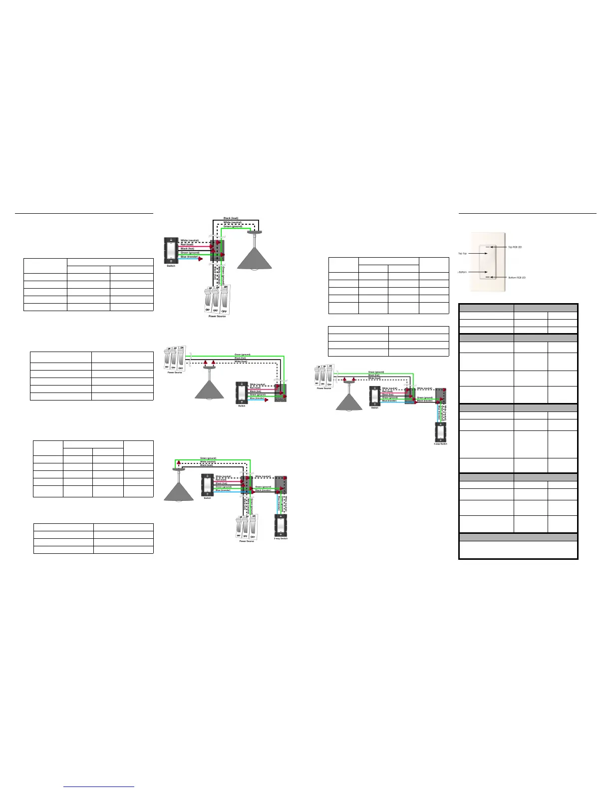
Sample Wiring Configurations
Single-Switch Environment—Power Source at Wall Box
To wire the switch for a Control4 single-switch environment when the power is
coming from the wallbox, connect together and cap with a wire nut the wires
indicated in the following table:
Single-Switch Environment—Power Source at Light
Fixture
To wire the switch for a Control4 single-switch environment when the power is
coming from the light fixture (switched-leg mode), connect together and cap
with a wire nut the wires indicated in the following table:
3-Way-Switch Environment—Power Source at Wall Box
To wire the switch for a Control4 3-way-switch environment when the power is
coming from the wall box, do the following:
1. Wire the switch to Wall Box 1 by connecting together and capping with a
wire nut the following wires:
2. Wire the 3-way switch to Wall Box 2 by connecting together and capping
with a wire nut the following wires:
3-Way-Switch Environment—Power Source at Light
Fixture
To wire the switch for a Control4 3-way-switch environment when the power is
coming from the light fixture (switched-leg mode), do the following:
1. Wire the switch to Wall Box 1 by connecting together and capping with a
wire nut the following wires:
2. Wire the 3-way switch to Wall Box 2 by connecting together and capping
with a wire nut the following wires:
Operation and Configuration
To configure this switch for use with a
Control4 system, refer to the
documentation that shipped with your
controller. To operate and configure
this switch as a stand-alone device,
refer to the tables below.
This switch features
RGB LEDs, which
are small lights that can be programmed
with different colors to reflect different states
or color preferences.
Note: The Switch may feel warm to
the touch under normal operation.
Wires from switch Wires from Wall Box
Light Fixture Power Source
White (neutral) White (neutral) White (neutral)
Red (load) black (load) None
Black (hot) None Black (hot)
Green (ground) Green (ground) Green (ground)
Blue (3-way traveller) None None
Wires from switch Wires from the Wall Box (coming
from the power source at light)
White (neutral) White (load)
Red (load) White (load)
Black (hot) Black (hot)
Green (ground) Green (ground)
Blue (3-way traveller) None
Wires from
switch
Wires from Wall Box 1 Wires from Wall
Box 2
Light Fixture Power Source
White (neutral) White (neutral) White (neutral) White (neutral)
Red (load) black (load) None None
Black (hot) None Black (hot)
Green (ground) Green (ground) Green (ground) Green (ground)
Blue (3-way
traveller)
None None Black (3-way
traveller)
Wires from 3-way Keypad Wires from Wall Box 2
White (neutral) White (neutral)
Green (ground) Green (ground)
Blue (3-way traveller) Black (3-way traveller)
Wires from
switch
Wires from Wall Box 1 Wires from Wall
Box 2
Light Fixture Power Source
White (neutral) White (load) None White (neutral)
Red (load) White (load) None None
Black (hot) None Black (hot) None
Green (ground) None Green (ground) Green (ground)
Blue (3-way
traveller)
None None Black (3-way
traveller)
Wires from 3-way Keypad Wires from Wall Box 2
White (neutral) White (neutral)
Green (ground) Green (ground)
Blue (3-way traveller) Black (3-way traveller)
Operate Switch Expected behavior of RGB LEDs:
To operate switch: Top Bottom
Turn ON: Tap top. Lit, full brightness Not lit
Turn OFF: Tap bottom. Not lit Lit, full brightness
Bind 3-Way Status indicated by RGB LEDs
To bind devices for a 3-Way
switch:
Top Bottom
1. Tap bottom 6 times on each
device in the 3-Way group to
enter into 3-Way Binding
mode.
Red = Ready to
receive and build an
address table
Amber = 3-Way
Binding mode
2. Tap top 1 time on each
device in the 3-Way group
to advertise its address.
Green = Device
address has been
advertised
Amber = 3-Way
Binding mode
3. Tap bottom 1 time to save
all advertised addresses
and exit 3-Way Binding
mode.
(Returns to default
or previous value)
(Returns to
default or
previous value)
Select Channel Status indicated by RGB LEDs
To select a channel: Top Bottom
1. Tap bottom 7 times to enter
into Channel Select mode.
Red = Channel A Aqua = Channel
Select mode
2. Tap top 1 time to toggle to
next available channel.
Red = Channel A
Blue = Channel B
Green = Channel C
(Other user defined
color) = Custom
Channel
Aqua = Channel
Select mode
3. Tap bottom 1 time to save
selected channel and exit
Channel Select mode.
(Returns to default
or previous value)
(Returns to
default or
previous value)
Restore Defaults Status indicated by RGB LEDs
To restore default settings: Top Bottom
1. Tap bottom 10 times to enter
into Restore Default mode.
Red = No action White = Restore
Default mode
2. Tap top 1 time to toggle to
No Action or Restore
Default modes.
Red = No action
Green = Restore
Default
White = Restore
Default mode
3. Tap bottom 1 time to
execute the selected
command and exit Restore
Default mode.
(Returns to default
or previous value)
(Returns to
default or
previous value)
Care and Cleaning
Do NOT paint switch or wall plate. It is not recommended.
Do NOT use any chemical cleaners to clean the switch.
Clean surface with a soft damp cloth as needed.
 Loading...