TRIAD INSTALLATION GUIDE - 8×8 and 24×24 AUDIO MATRIX SWITCH
www.control4.com | 1-888-400-4072 | DOC-00287-A 2017-08-28 DH
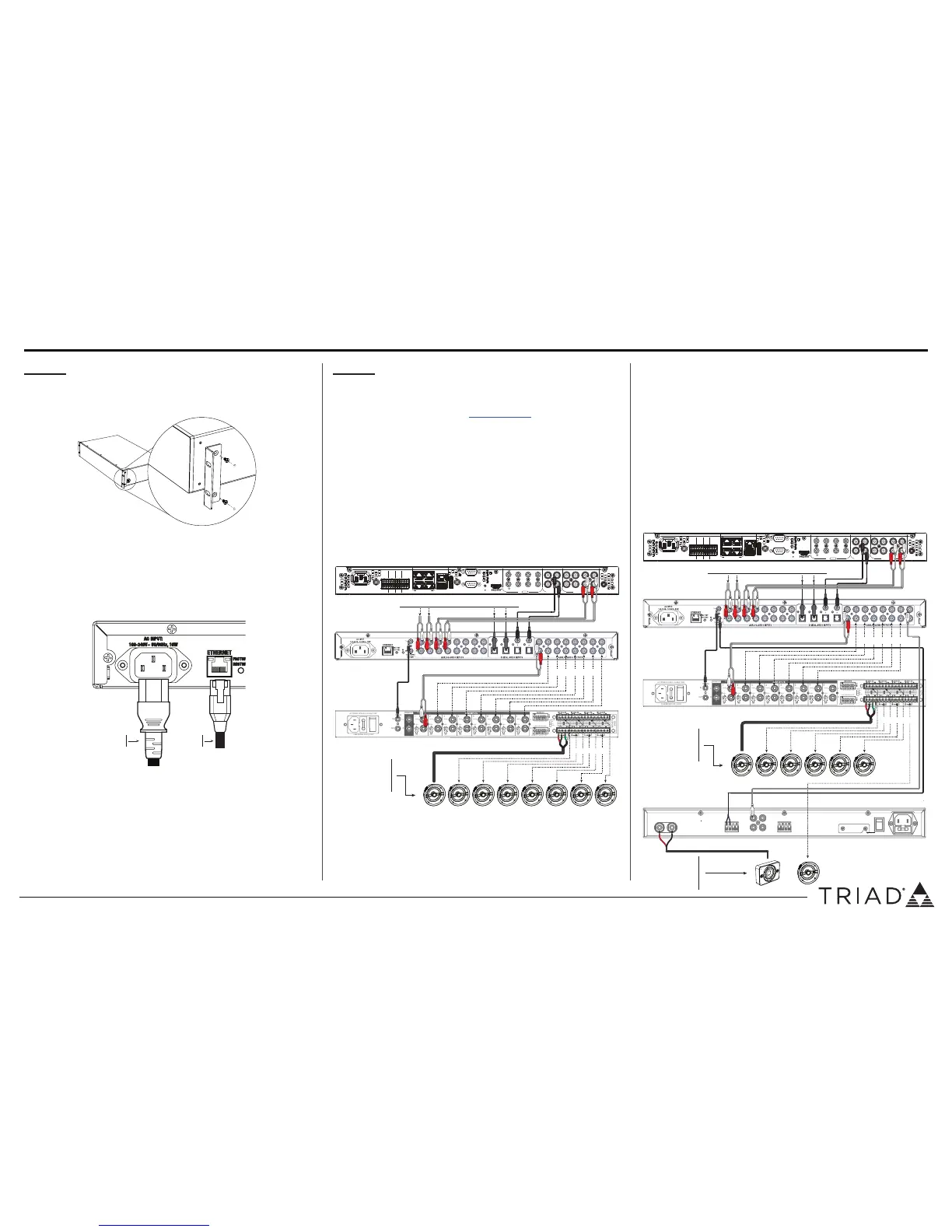
INSTALLING THE MATRIX SWITCH IN A RACK
1 Align the holes on the rack ears with the holes on both sides of the
matrix switch. The matrix switch can be rear or front mounted.
2 Attach the rack ears to the matrix switch using the provided screws.
CONNECTING THE MATRIX SWITCH TO ETHERNET AND
POWER
1 Plug the Ethernet CAT5E/6 cable from a local network connection into
the ETHERNET port.
2 Connect the provided power cable into the back of the Audio Matrix
Switch to the power outlet. When the power cable is connected, the
Audio Matrix Switch should power up.
CONNECTING AUDIO TO THE MATRIX SWITCH
Physical and programming connections are required to control, navigate,
and use the Audio Matrix Switch as designed. Use Composer Pro to add
the driver to the desired room and set up the programming connections.
See the Composer Pro User Guide (ctrl4.co/cpro-ug) for details.
Connect the physical connections to your audio matrix switch from your
other audio equipment using the examples provided below:
CONNECTING AN 8 SOURCE, 8 ZONE SYSTEM
1 Connect audio sources (outputs from a Control4 controller, audio
streaming devices, tuners, etc.) to the ANALOG AUDIO INPUT and
DIGITAL AUDIO INPUT jacks.
2 Connect the ANALOG AUDIO OUTPUT jacks to amplifiers or amplified
speakers.
3 Connect 12V trigger cables from the matrix switch to the amplifier (if
applicable) for automatic power control of the amplifier.
ADDING A SUBWOOFER TO A ZONE USING THE 2.1 ZONE
FEATURE
Using the 2.1 Zone feature, you can group two outputs of the matrix and
one output can feed a subwoofer amplifier. Repeat steps 1-3 for the 6
standard speaker zones as described in “Connecting an 8 source, 8 zone
system”.
1 Set up 2.1 grouping in Composer > System Design > driver for the
matrix switch. See the Composer Pro User Guide for more details.
2 Set the assignable 12V trigger output (ASG) to the output for the
subwoofer amplifier in Composer > System Design > driver for the
matrix switch.
3 Connect the matrix switch Analog Audio Output to the Audio Input of
the amplifier for the subwoofer.
4 Connect the ASG 12V output to the 12V trigger input of the amplifer.
Ethernet
cable
Power
cable
 Loading...