Quick Guide iDFace Version 1.1 Control iD 2021 ©
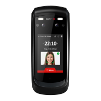
For the identification process, position yourself in front
wait for the indication of access allowed or denied in the
Avoid using objects that can block the capture of
images of the eyes.
The recommended distance between the device and
the user (1.45 1.80m tall) is from 0.5 to 1.4 meters.
Please make sure the user is positioned in the
field of view.
Electronic lock types
iDFace, through the relay in the External Access Module,
is compatible with almost all of the locks available in the
market.
Magnetic lock
The magnetic or electromagnetic lock consists of a coil
(fixed part) and a metal part (armature plate) which is
attached to the door (mobile part). While there is a
current passing through the magnetic lock, the fixed part
will attract the mobile part. When the distance between
these two parts is small, ie. when the door is closed and
the dock is on top of the fixed part, the attraction force
between the parts can reach over 1000kgf.
Thus, the magnetic lock is normally connected to the NC
contact of the activation relay, as we normally want for
the current to go through the electromagnet and, if we
want the door to open, the relay must open and interrupt
the current flow.
In this guide, the magnetic lock will be represented by:
Electric bolt
The electric bolt lock, also known as solenoid lock,
consists of a fixed part with a mobile pin connected to a
solenoid. The lock normally comes with a metal plate that
will be attached to the door (mobile part).
The pin on the fixed part enters the metal plate
preventing the door from opening.
In this guide, the solenoid pin lock will be represented by:
The gray terminals may not be present in all locks. If
there is a power supply connection (+ 12V or + 24V), it is
essential to connect it to a source before operating the
lock.
Electromechanical Lock
The electromechanical lock or strike lock consists of a
latch connected to a solenoid through a simple
mechanism. After opening the door, the mechanism
returns to its initial state allowing the door to be closed
again.
Thus, the electromechanical lock typically has two
terminals connected directly to the solenoid. When
current passes through the lock, the door will be
unlocked.
In this guide, the electromechanical lock will be
represented by:
Confirm the operating voltage of the lock before
connecting it to the iDFace! Many
electromechanical locks operate at 110V/220V and
must therefore use a different wiring set up.
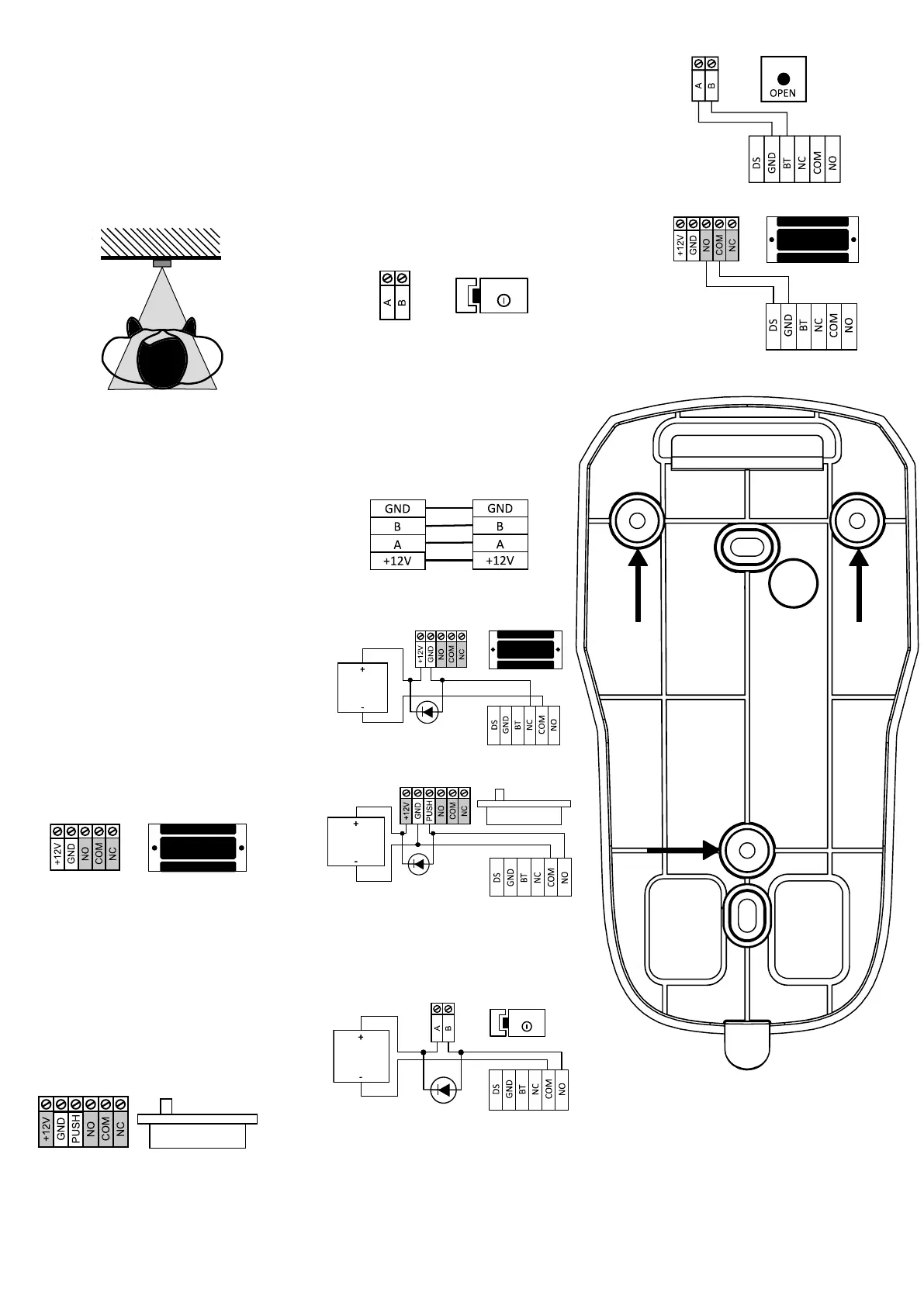
Wiring Diagrams
iDFace and EAM (Mandatory)
Magnetic Lock
Solenoid Pin Lock (Fail Safe)
We recommend the use of a dedicated power
supply to source power to the Solenoid Lock.
Electromechanical Lock (Fail Secure)
We recommend the use of an exclusive power
supply to source power to the Electromechanical Lock.
Push Button
Door Sensor
Reference pattern for installation
 Loading...