Do you have a question about the Cooper Menvier 100 and is the answer not in the manual?
Provides safety advice and defines key terms used in the installation guide.
Lists available supplementary guides for system operation, engineering, and software.
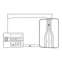
Describes the Menvier40/100 control units, their hardware, zone capacity, and system integration.
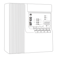
Details the built-in and add-on communication modules for alarm reporting and remote maintenance.
Explains the two system modes: Part Setting and Ward Based System.
Covers essential site survey steps, detector assessment, and radio expander placement.
Guides signal strength testing for radio expanders using specific meters and transmitters.
Explains the purpose of the guide and references other essential documentation.
Provides guidelines for optimal placement of the control unit and wired zone expanders.
Offers advice on siting keypads to avoid interference and ensure user accessibility.
Details recommended and prohibited locations for wireless zone expanders.
Advises on standard precautions for handling static-sensitive printed circuit boards.
Provides step-by-step instructions with a diagram for opening the control unit housing.
Identifies the various controls, display, and LEDs on the i-kp01 keypad.
Details the procedure for safely opening the i-kp01 keypad for access.
Explains how to open both wired and radio expander cases.
Calculates required current and battery capacity for mains failure standby.
Specifies cable types, segregation, configuration, and length for the bus system.
Illustrates bus wiring configurations: Daisy Chain and Star.
Explains the use and application of termination jumpers on the RS485 interface.
Details voltage drop calculations and recommendations for maintaining minimum voltage levels.
Suggests doubling up supply connections to halve resistance and voltage drop.
Recommends using separate cores for detection devices to reduce voltage drop.
Describes when and how to install remote power supplies to meet demand.
Warns about handling electronic components sensitive to static electricity.
Covers marking fixing points, fitting feet, tamper shroud, and securing the case to the wall.
Instructs on how to correctly clip the PCB tray into the control unit case.
Details connecting the transformer wires to the 20Vac connector on the PCB.
Explains how to fit the tamper bracket and switch, and connect it to the PCB.
Refers to cabling requirements for the bus cable installation.
Provides guidelines for keypad placement and mounting the back box.
Shows diagram for connecting keypads to the control unit bus.
Explains how the control unit assigns addresses to bus devices.
Details how to configure keypad backlight and LED behavior using jumpers.
Describes how to adjust non-alarm tone volume using the keypad sounder control.
Explains the function and use of an engineering keypad for system programming.
Covers mounting wired and radio expanders using screws and identifying fixing holes.
Details connecting expanders to the bus cable via their PCB connectors.
Explains the process of assigning addresses to expanders via the Installer Menu.
Describes the role of expander loudspeakers for tones and alarms.
Provides safety warnings and instructions for connecting the control unit to the mains supply.
Emphasizes disconnecting mains power and using proper safety devices during connection.
Details wiring for CC and FSL detectors on control units and expanders.
Illustrates wiring for 4-wire CCL zones on the control unit and wired expander.
Explains connecting 2-wire CCL detectors and specifying zone type.
Shows wiring for FSL zones on the control unit, including example resistor values.
Illustrates FSL wiring for control units and expanders, including resistor value notes.
Shows examples for wiring multiple detectors per zone and for double doors.
Demonstrates wiring a trouble/masking output using the 3-resistor method.
Details connection of control unit wired outputs, including relay and transistor types.
Provides methods for connecting wired sounders using control unit outputs.
Explains connecting external equipment to the AUX TAMP terminals for tamper detection.
Describes the transistor-driven outputs available on wired expanders.
Illustrates wiring external sounders to wired expanders using CC or FSL methods.
Details connecting optional loudspeakers to control units and expanders.
Explains connecting the internal communicator to the telephone network.
Lists uses for the communicator: alarm transmission and PC connection for diagnostics.
Recommends using an ex-directory line exclusively for alarm communications.
Describes the control unit's line monitoring feature for detecting telephone line failures.
Explains how to program test calls to an Alarm Receiving Centre (ARC).
Covers communicator suitability, network types, and approval compliance.
Identifies SELV and TNV connectors and stresses correct terminal usage for safety.
Details connecting the telephone line to the internal communicator and safety considerations.
Explains fitting an ADSL filter when sharing the telephone line with broadband service.
Provides steps for connecting a separate communicator using a wiring harness.
Details the wiring harness connections for plug-by communicators.
Instructs on fitting the 17Ah battery, noting weight and safety requirements.
Describes the initial power-up process, including potential alarm tones and LED indications.
Details how to enter the Installer Menu and initial keypad display prompts.
Guides selection of Ward/Part Set mode and Security Grade (2 or 3).
Explains how to set the wiring type for control unit zones.
Covers the process of assigning addresses to keypads and expanders via the Installer Menu.
Explains the meaning of diagnostic LED flashing sequences on expander PCBs.
Describes how to transfer an Installer Menu session to another keypad.
Provides steps to exit the Installer Menu and save changes.
Emphasizes the importance of leaving the Installer Menu to save configuration changes.
Details how to re-access the Installer Menu after exiting, including default codes.
Explains the procedure for restoring factory default access codes and deleting user data.
Describes how to reset system options to factory defaults without clearing access codes.
Outlines steps for system commissioning, including installing peripherals and programming.
Covers teaching peripherals to the system and performing walk tests.
Guides system programming and keypad allocation to wards.
Instructs on reassembling the control unit lid and testing tampers.
Details user training on system operation and providing the Administrator's Guide.
Lists checks for damage, tamper action, battery condition, and cabling during annual inspection.
Provides instructions for cleaning keypads and lenses of PIR detectors.
Recommends testing all buttons, detectors, sounders, and strobes.
Details product name, description, manufacturer, environmental specs, and case material.
Lists the capacities for zones, outputs, keypads, expanders, etc., for the Menvier40.
Lists the capacities for zones, outputs, keypads, expanders, etc., for the Menvier100.
Summarizes capacities for outputs, keypads, loudspeakers, and plug-on modules for both models.
Details specifications for panel outputs, plug-by outputs, and expander outputs.
Provides sounder volume levels (dB) for keypads and loudspeakers.
Mentions the control unit's fuse and compliance with electrical safety standards.
Specifies security grades and technical details for radio detectors.
Details power supply type, mains requirements, total capacity, and auxiliary supplies.
Outlines EN50131-6 ratings for security grade 3 installations and battery standby time.
States compliance with EN50130-4 (Immunity) and EN61000-6-3 (Emissions).
Details the voltage-free relay contacts and open collector transistor outputs.
Shows current draw for control unit, keypads, expanders, and communicators.
Specifies cable requirements for PC connection via Ethernet or USB ports.
Lists operating frequencies and transmitter ranges for radio peripherals.
Details compliance with EN50130-5, PD 6662, and EN50131 standards.
Lists various compatible equipment such as keyfobs, detectors, and receivers.
Lists additional modules like Ethernet, speaker boxes, relay cards, and keypads.
Details specific expander models (EXP-W10, EXP-R10, EXP-R30) and keypad versions.
Lists specific device types like Radio PIR, Pet tolerant PIR, and Wired PIR.
| Brand | Cooper |
|---|---|
| Model | Menvier 100 |
| Category | Security System |
| Language | English |