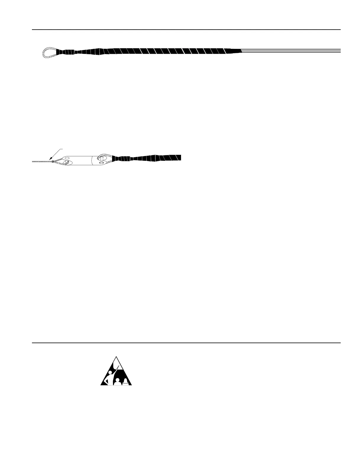
Figure 6
5.4 Figure 6 illustrates a completed grip.
5.5 Connect the pulling eye to the appropriate ball
bearing swivel and pull line or tape (Figure 7). The grip is
now ready for cable placing.
Figure 7
Note: Refer to the cable specification sheet for maximum pulling
tension during installation.
6. Grip Removal
6.1 After completion of the pull, cut the cable 90 cm
(36 in.) behind the grip. Place a protective cap over the
exposed cable end and tape it in place to prevent water or
dirt intrusion. Store coiled slack so that it is protected
from damage.
Issue 5 SRP-005-033 Page 3
Corning Cable Systems reserves the right to improve, enhance, and modify
the features and specifications of Corning Cable Systems’ products without
prior notification.
All trademarks are the property of their respective holders
Corning Cable Systems is ISO 9001 certified.
© 2000, 2002 Corning Cable Systems LLC. All rights reserved.
Printed in U.S.A.
Corning Cable Systems LLC
PO Box 489
Hickory, NC 28603-0489 USA
For US and Canada 1-800-743-2673
International 828-901-5000
FAX: 828-901-5973
http:www.corning.com/cablesystems
Corning Cable Systems offers comprehensive, integrated training
programs. Courses are structured for: Telephony, CATV, LAN,
Intelligent Transportation Systems and Power Utilities.
For information on Engineering Services Training call:
800-743-2671.
Special Note:
Fiber Optic
Training
Program
 Loading...