included fan extension cables can be used if necessary.
4. Connect the thermal sensors to the 2-pin headers labeled “Temp 1-4”.
TIP: The thermal sensors are designed to measure ambient temperatures, so for the most
accurate results, they should not directly touch components. You may find it useful to mount the
thermal sensors near air intake and exhaust points, and if your PC case has multiple
compartments, you can try placing each of the sensors in its own compartment. Since the thermal
sensors can easily be repositioned, you can try various locations and use what works best for you.
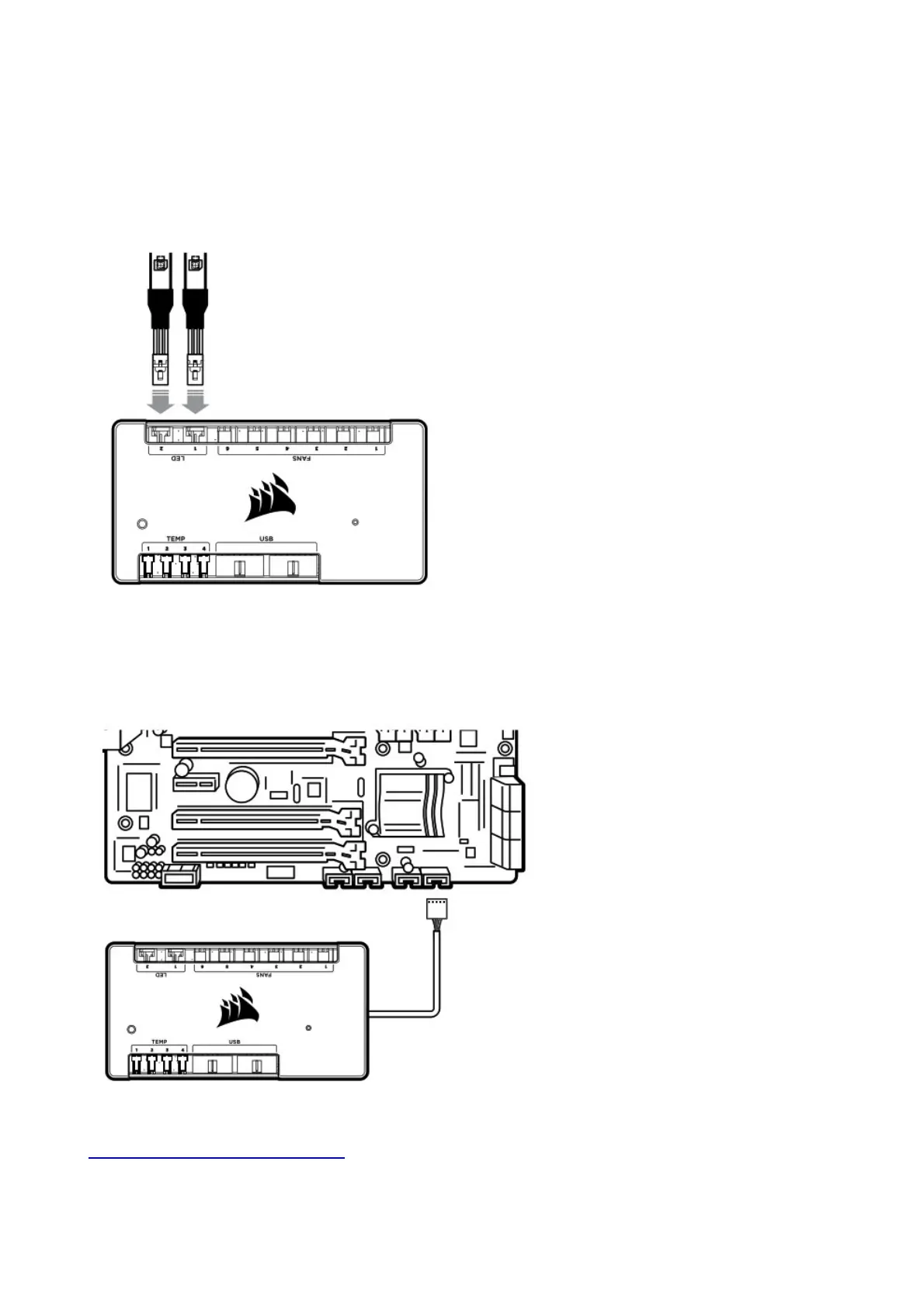
5. OPTIONAL: Connect the individually addressable RGB LED strips (sold separately) to the 3-pin
connectors labeled “LED 1-2”. Alternatively, connect your CORSAIR RGB fans to the Commander
PRO via the RGB LED hub (sold separately) using the supplied RGB LED hub cables.
WARNING! Please refrain from mounting the strips
on components (HDD, SSD) that are sensitive to magnets.
6. Connect compatible iCUE components such as the Lighting Node PRO (sold separately) into an
available 9-pin USB 2.0 header on the Commander PRO. Ensure that these devices are properly
powered (see device manual).
7. Plug the USB cable from the Commander PRO into an available internal USB 2.0 header on your
PC’s motherboard (refer to your motherboard manual for location).
8. Connect the SATA power connector to any available SATA connector from your power supply.
9. Internet connection is required to download the latest CORSAIR iCUE software at
www.corsair.com/downloads.