18
E 136 - XTA 624 C1 Eng. 22.11.10 AM REV. 02
We reserve the right to make changes without notice
COSTER
M0. NORMAL USE
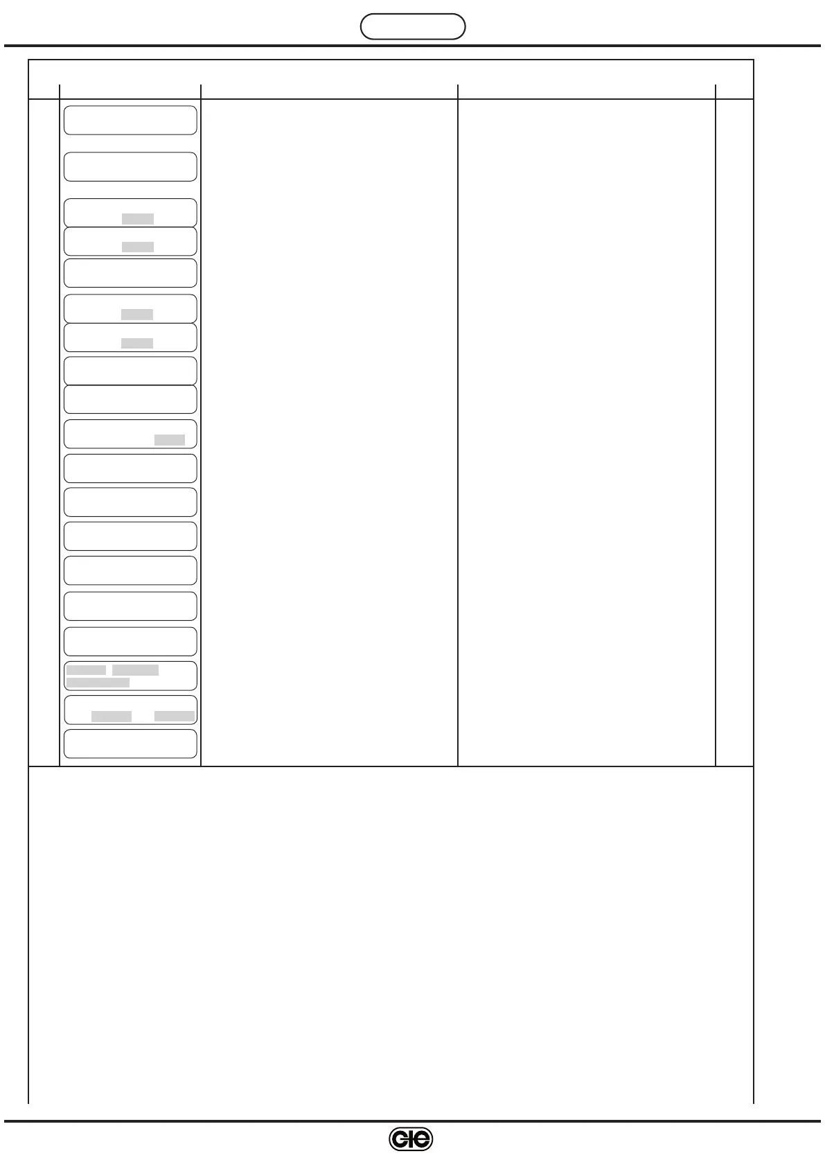
Ref. Display Description Notes Sect.
S i t e - - - - - - - - - - - -
R o o m T . : 2 0 . 0 c
M0.1
Site name.
Actual temperature
22.
2
Set in M2.13
Roon temp. : if B3 or B1 and B3 are connected
Floow temp. : if only B1 is connected
C u r r e n t m o d e :
O N W i n t e r
M0.2
Current mode : – ON; OFF.
– ON Winter ; OFF Winter.
– ON Summer ; OFF Summer.
15.
5
Mode is determined by Season Switching (M2.2)
and output D-E1-E2
H e a t T . R o o m
D e s i r . : 2 0 . 0 c ± 0 . 0
M0.3
Required heating temperature and adjustment
through set point adjuster Rt° (only if configured)
15.
1
Displayed if B3 or B1 and B3 are connected, and
if M2.
4 or M2.6 setting is HEATING
Displayed only if B1 is connected, and if M2.
4 or
M2.
6 setting is HEATING
H e a t T . F l o w
D e s i r . : 2 0 . 0 c ± 0 . 0
F l o w H e a t T .
C o m p e n s a t . : ± 0 0 . 0
M0.4
Compensation of heating flow temperature as
calculated by the controller
16.
Displayed if B1 and B2 are connected and B3
is not connected, and if M2.
4 or M2.6 setting is
HEATING
C o o l . T . R o o m
D e s i r . : 2 5 . 0 c ± 0 . 0
M0.5
Required cooling temperature and adjustment
through set point adjuster Ht° (only if configured)
15.
1
C o o l . T . F l o w
D e s i r . : 2 5 . 0 c ± 0 . 0
Displayed if B3 or B1 and B3 are connected, and
if M2.
4 or M2.6 setting is COOLING
Displayed if only B1 is connected, and if M2.
4 or
M2.
6 setting is COOLING
C o o l . T . F l o w
C o m p e n s a t . : ± 0 0 . 0
M0.6
Compensation of cooling temperature as calculated
by the controller
16.
Displayed if B2 and B3 or B1, B2 and B3 are con
-
nected, and if M2.
4 or M2.6 setting is COOLING
Displayed if B2 with B1 only is connected, and if
M2.
4 or M2.6 setting is COOLING
C o o l . T . F l o w
C o m p e n s a t . : ± 0 0 . 0
P r e h e a t i n g T .
D e s i r . : 1 8 . 0 c
M0.7
Desired Preheating temperature
17.
Displayed if B4 is connected, and if M2.4 or M2.6
setting is PREHEATING
C a l c u l a r e d F l o w
H e a t i n g T . : 2 2 . 0 c
M0.8
Calculated flow temperature based on Heating
control
22.
3
Displayed if B1 and B3 are connected, and if M2.4
or M2.
6 setting is HEATING
C a l c u l a r e d F l o w
C o o l i n g T . : 3 5 . 0 c
M0.9
Calculated flow temperature based on Cooling
control
22.
3
Displayed if B1 and B3 are connected, and if M2.4
or M2.
6 setting is COOLING
F l o w T . : 2 2 . 0 c
P r e h e a t T . : 1 5 . 0 c
M0.10
Actual flow temp. as measured by B1
Preheating temp. as measured by B4
22.
3
Flow T.: Displayed if B1 and B3 are connected
Preheat. T.: Displayed if B4 is connected
Y 1 - H e a t i n g . : 1 0 0 %
Y 2 - C o o l i n g . : 1 0 0 %
M0.12
Value of load assigned to output Y1
Value of load assigned to output Y2
22.
3
Y1 - Y2 : PREHEAT; HEATING; COOLING; OFF
1 2 . 1 8 M O N D A Y
1 0 . 0 3 . 0 0 G M T
M0.14
Setting: time of day, day of week and date
Current time: GMT, BST
For data recording only.
Dates for BST (daylight saving time) to be set in
M0.
15
S u m m e r T i m e
F r : 2 6 . 0 3 t o : 2 8 . 1 0
M0.15
BST (daylight saving time) start and end dates
For data recording only.
X T A 6 2 4
V e r s . x x
M0.16
Controller ID data
O u t s i d e T . : – 2 . 0 c
M0.11
Outside temp. as measured by B2
22.
3
Outside t.: Displayed if B2 is connected
Y s - D A M P . T E M : 1 0 0 %
M0.13
Value of load assigned to output Ys
22.
3
Ys : DAMP.TEM.; RECUPERATOR
 Loading...