Cozy III
Pilot’s Operating Handbook Page 12
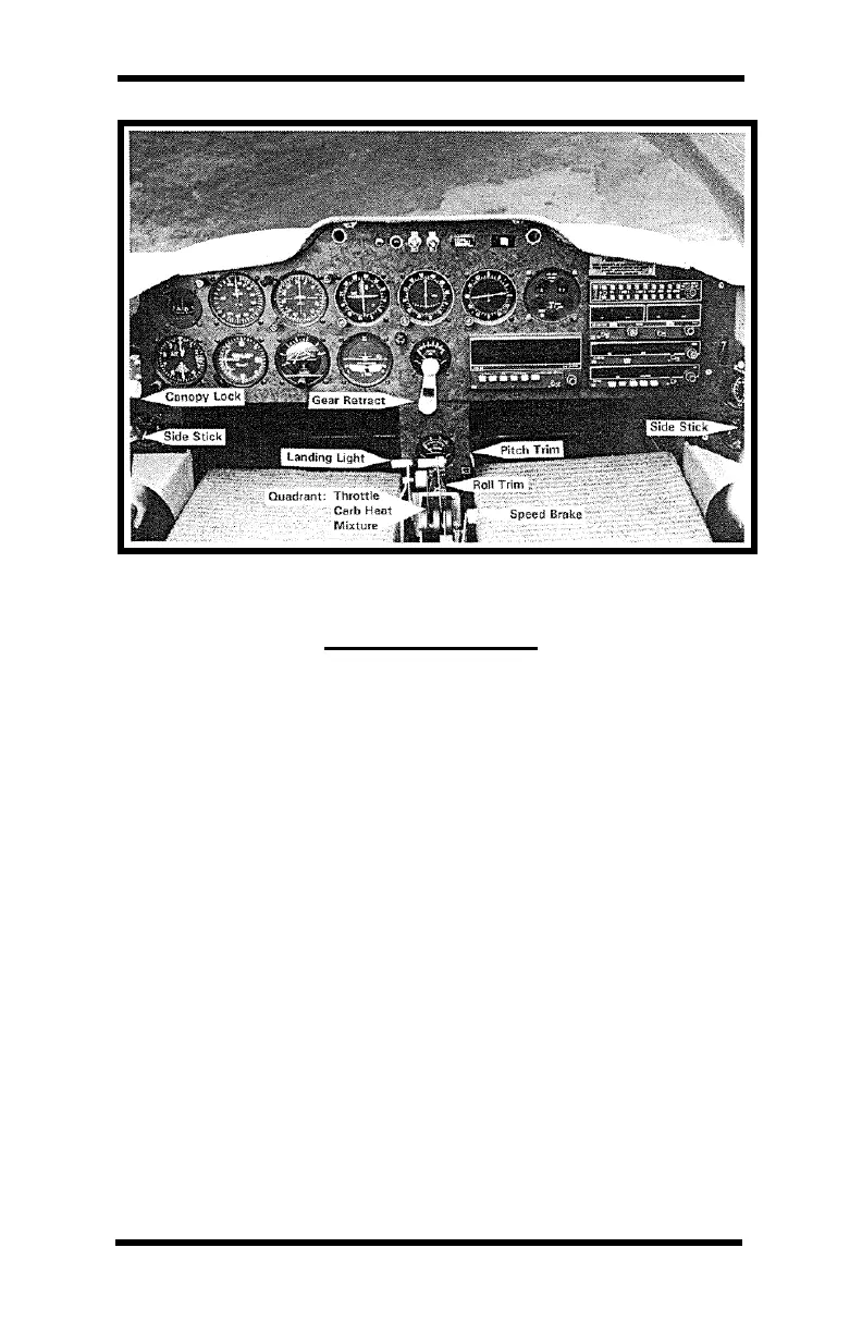
Figure 2: Cozy III Instrument Panel & Control Arrangement
FUEL SYSTEM
The fuel system consists of two 25 gal. individually selectable
wing tanks. A three way selector (left, right, and off) is located in
the center of the front seat back. There is no provision for cross
feed (nor is it desirable) so fuel can be used from only one tank
at a time. Two fuel sump blisters located under each fuel tank at
the fuselage juncture assure fuel supply to the engine in all
normal flight attitudes. Each tank is individually vented. Vent
location is in the sheltered, high-pressure area under each
strake. A mechanical engine-driven fuel pump transfers fuel from
the tanks to the carburetor. An auxiliary electric fuel pump
provides backup for the engine-driven pump, should it ever fail.
Fuel pressure is indicated on a gauge in the cockpit. The electric
pump should be turned on if the mechanical pump fails as
indicated by loss of pressure. The electric fuel pump should also
be used to provide fuel pressure redundancy during low altitude
operation, such as takeoff and landing.
There are three fuel drains on the airplane, one in the leading
edge of each fuel tank strake, and one on the gascolator
mounted on the firewall. The gascolator is easily accessible
through the air scoop under the cowling for draining during
preflight. To prevent overfilling the fuel tanks, exceeding the
gross weight limitations, the tanks cannot be completely filled