EasyManua.ls Logo

CPC 485 - Page 4

Default Icon
8 pages
Print Icon
To Next Page IconTo Next Page
To Previous Page IconTo Previous Page
Loading...
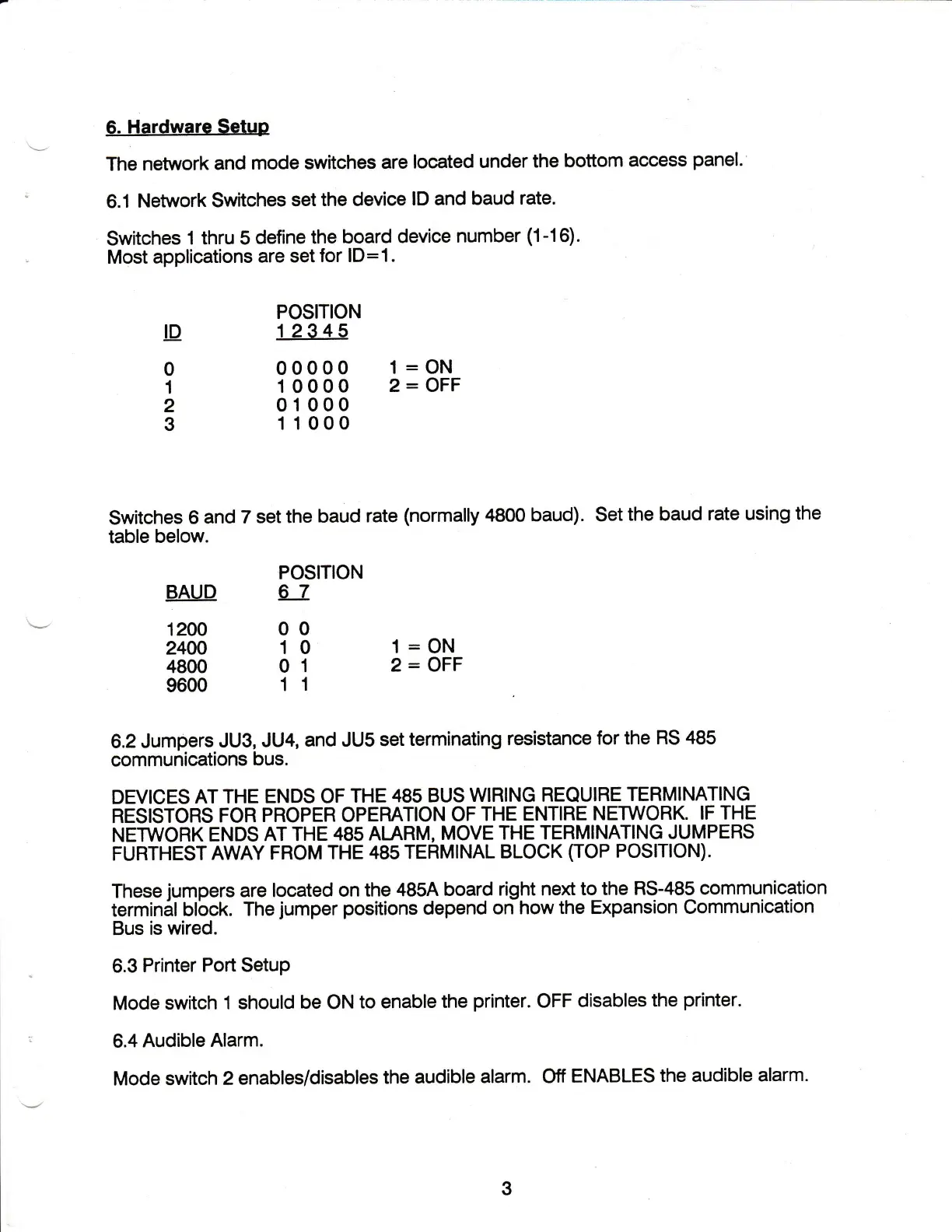
6.
Hardware
Setup
The
network
and
mode
switches
are located
under
the
bottom
access
panel.
6.1
Netnvork
Switches
set
the device
lD
and
baud rate.
Switches
1 thru 5
define
the
board
device
number
(1-16).
Most
applications
are
set for
lD=1.
POSITION
!D
12345
0
00000
l=ON
1
10000
2=OFF
2
01000
3
1 1000
Switches
6
and
7 set
the baud
rate
(normally
4800
baud). Set
the
baud
rate using
the
table below.
POSITION
BAUD
AJ.
\-'
12oo
o
o
24W
10
l=ON
4800
01
2=OFF
9600
1 1
6.2
Jumpers
JU3,
JU4,
and JUS
set
terminating
resistance
for the
RS
485
communications
bus.
DEVICES
AT THE
ENDS OF
THE
485 BUS
WIHING REQUIRE
TERMINATING
RESISTORS
FOR
PROPER OPERATION
OF
THE
ENTIRE
NETWORK.
IF
THE
NETWORK
ENDS
AT
THE
485 ALARM,
MOVE
THE
TEBMINATING JUMPERS
FUHTHEST
AWAY FROM
THE
48s TEHMINAL
BLOCK
(TOP
POSITION).
These
jumpers
are located
on
the 485A
board
right next
to the BS-485
communication
terminal
blbck.
The
jumper
positions
depend
onhow
the Expansion Communication
Bus is wired.
6.3
Printer
Port Setup
Mode
switch
1 should
be
ON
to enable
the
printer.
OFF
disables
the
printer.
6.4
Audible
Alarm.
Mode switch
2
enables/disables
the
audible
alarm. Off
ENABLES
the audible
alarm.
3