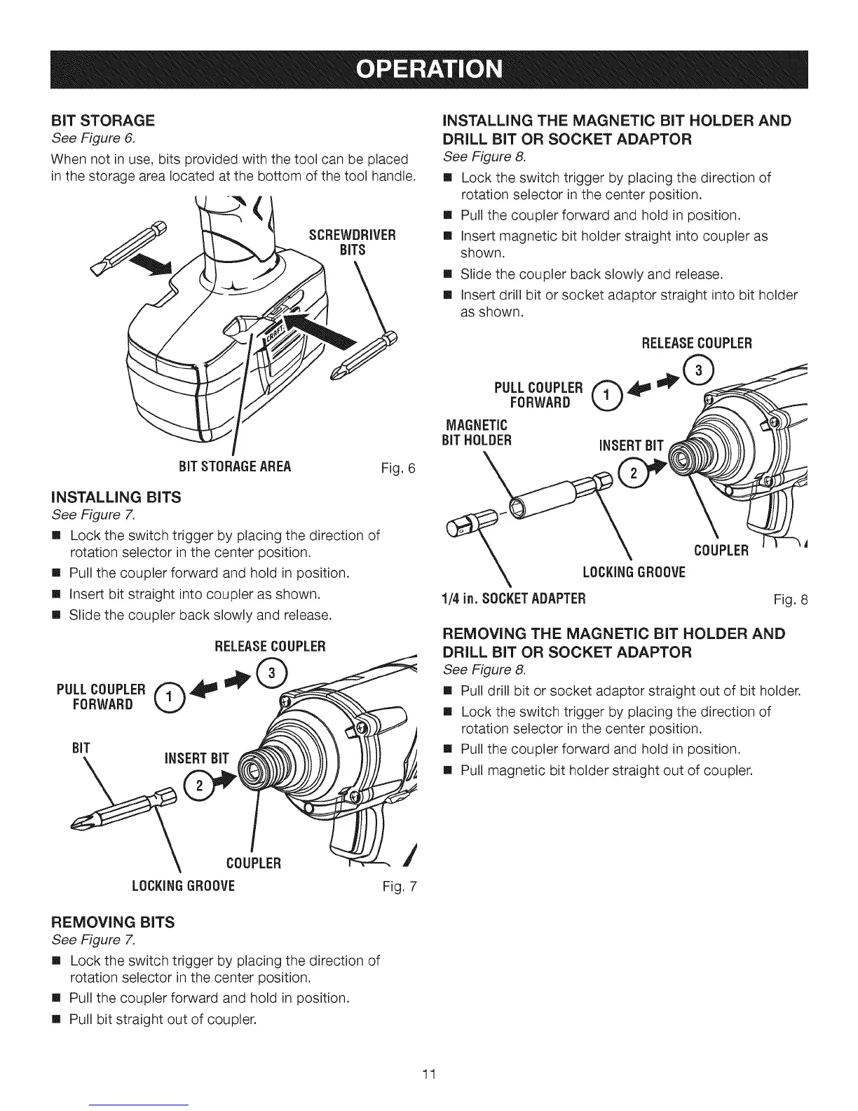
BIT STORAGE
See Figure 6.
When not in use, bits provided with the tool can be placed
in the storage area located at the bottom of the tool handle.
(
SCREWDRIVER
BiTS
INSTALLING THE MAGNETIC BIT HOLDER AND
DRILL BIT OR SOCKET ADAPTOR
See Figure 8.
[] Lock the switch trigger by placing the direction of
rotation selector in the center position.
[] Pull the coupler forward and hold in position.
[] insert magnetic bit holder straight into coupler as
shown.
[] Slide the coupler back slowly and release.
[] insert drill bit or socket adaptor straight into bit holder
as shown.
RELEASECOUPLER
BIT STORAGEAREA Fig. 6
INSTALLING BITS
See Figure 7.
[] Lock the switch trigger by placing the direction of
rotation selector in the center position.
[] Pull the coupler forward and hold in position.
[] Insert bit straight into coupler as shown.
[] Slide the coupler back slowly and release.
RELEASECOUPLER
LOCKINGGROOVE
REMOVING BITS
See Figure 7.
[] Lock the switch trigger by placing the direction of
rotation selector in the center position.
[] Pull the coupler forward and hold in position.
[] Pull bit straight out of coupler.
/
Fig. 7
PULLCOUPLERQ,_
FORWARD
MAGNETIC
BITHOLDER INSERTBIT
LOCKINGGROOVE
1/4 in. SOCKETADAPTER
COUPLER
Fig. 8
REMOVING THE MAGNETIC BIT HOLDER AND
DRILL BIT OR SOCKET ADAPTOR
See Figure 8.
[] Pull drill bit or socket adaptor straight out of bit holder.
[] Lock the switch trigger by placing the direction of
rotation selector in the center position.
[] Pull the coupler forward and hold in position.
[] Pull magnetic bit holder straight out of coupler.
11

 Loading...