ERVICE AN ADJUSTMENTS
/
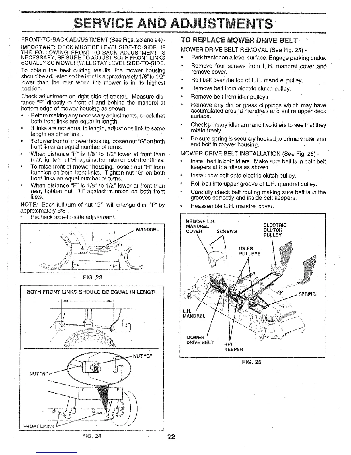
FRONT-TO-BACK ADJUSTMENT (See Figs. 23 and 24)°
iMPORTANT: DECK MUST BE LEVEL SIDE-TO-SIDE. iF
THE FOLLOWING FRONT-TO-BACK ADJUSTMENT tS
NECESSARY, BE SURETO ADJUST BOTH FRONT LINKS
EQUALLY SO MOWER WILL STAY LEVEL SIDE-TO-SIDE.
To obtain the best cutting results, the mower housing
should be adjusted so the front isapproximately 1/8" to 1/2"
lower than the rear when the mower is in its highest
position,
Check adjustment on right side of tractor. Measure dis-
tance "F" directly in front of and behind the mandrel at
bottom edge of mower housing as shown.
Before making any necessary adjustments, check that
both front links are equal in length.
o If links are not equal in length, adjust one link to same
length as other link.
• To lowerfront of mower housing, loosen nut"G" on both
front links an equai number of turns.
• When distance "F" is 1/8" to 1/2" lower at front than
rear, tighten nut"H" against trunnion on both front links.
o To raise {font of mower housing, loosen nut "H" from
trunnion on both front links. Tighten nut "G" on both
front links an equal number of turns.
• When distance °'F" is I/8" to !/2" lower at front than
rear, tighten nut "H" against trunnion on both front
links,
NOTE: Each full turn of nut "G" wi!l change dim. "F" by
approximately 3/8".
Recheck side-to-side adjustment.
\
MANDREL
BOTH FRONT UNKS SHOULD BE EQUAL JNLENGTH
NUT "G"
NUT "N'
TO REPLACE MOWER DRaVE BELT
MOWER DRIVE BELT REMOVAL (See Fig. 25) -
- Park tractor on a level surface. Engage parking brake,
o Remove four screws from LH. mandrel cover and
remove cover.
Roll belt over the top of LH. mandrel pulley.
Remove belt from electric clutch pulley.
Remove belt from idter pulleys.
o Remove any dirt or grass clippings which may have
accumulated around mandrels and entire upper deck
surface.
® Check primary idler arm and two idlers to see that they
rotate freety.
o Be sure spring is securely hooked to primary idler arm
and bolt in mower housing.
MOWER DRIVE BELT INSTALLATION (See Fig. 25) -
o install belt in both idlers. Make sure belt is in both belt
keepers at the idlers as shown.
- install new belt onto electric clutch pulley.
o Rol! belt into upper groove of LH. mandrel pulley.
- Carefully check belt routing making sure belt is in the
grooves correctly and inside belt keepers.
® Reassemble L.H. mandrel cover.
REMOVE L,H,
MANDREL ELECTRIC
COVER SCREWS CLUTCH
PULLEY
iDLER
PULLEYS
SPRING
MANDREL
MOWER
DR_VE BELT BELT
KEEPER
.................................' F'iGi25 '
FiG, 24, 22