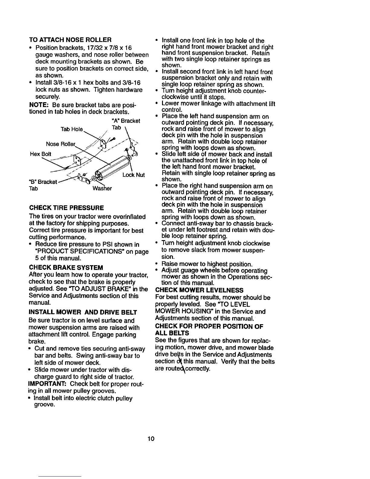
TOATTACHNOSEROLLER
• Position brackets, 17/32 x 7/8 x 16
gauge washers, and nose roller between
deck mounting brackets as shown. Be
sure to position brackets on correct side,
as shown.
• Install 3/8-16 x Ihex bolts and 3/8-16
lock nuts as shown. Tighten hardware
securely.
NOTE: Be sure bracket tabs are posi-
tioned in tab holes in deck brackets.
"A" Bracket
Tab Hole Tab \
Nose Roller _:_' "J' "_'_
<._ _ Lock Nut
"B" Bracketf "
Tab Washer
CHECK TIRE PRESSURE
The tires on your tractor were overinflated
at the factory for shipping purposes.
Correct tire pressure is impodant for best
cutting performance.
• Reduce tire pressure to PSI shown in
=PRODUCT SPECIFICATIONS" on page
5 of this manual.
CHECK BRAKE SYSTEM
After you leam how to operate your tractor,
check to see that the brake is properly
adjusted. See =TO ADJUST BRAKE" in the
Service and Adjustments section of this
manual.
INSTALL MOWER AND DRIVE BELT
Be sure tractor is on level surface and
mower suspension arms are raised with
attachment lift control, Engage parking
brake.
• Cut and remove ties securing anti-sway
bar and belts, Swing anti-sway bar to
left side of mower deck.
• Slide mower under tractor with dis-
charge guard to right side of tractor.
IMPORTANT: Check belt for proper rout-
ing in all mower pulley grooves.
• Install belt into electric clutch pulley
groove.
• Install one front link in top hole of the
right hand front mower bracket and right
hand front suspension bracket. Retain
with two single loop retainer springs as
shown.
• Install second front link in left hand front
suspension bracket only and retain with
single loop retainer spring as shown.
• Turn height adjustment knob counter-
clockwise until it stops.
• Lower mower linkage with attachment lift
control.
• Place the left hand suspension arm on
outward pointing deck pin. If necessary,
rock and raise front of mower to align
deck pin with the hole in suspension
arm. Retain with double loop retainer
spring with loops down as shown.
• Slide left side of mower back and install
the unattached front link in top hole of
the left hand front mower bracket.
Retain with single loop retainer spring as
shown.
• Place the right hand suspension arm on
outward pointing deck pin. If necessary,
rock and raise front of mower to align
deck pin with the hole in suspension
arm. Retain with double loop retainer
spring with loops down as shown.
• Connect anti-sway bar to chassis brack-
et under left footrest and retain with dou-
ble loop retainer spring.
• Turn height adjustment knob clockwise
to remove slack from mower suspen-
sion.
Raise mower to highest position.
Adjust guage wheels before operating
mower as shown in the Operations sec-
tion of this manual.
CHECK MOWER LEVELNESS
For best cutting results, mower should be
properly leveled. See =TO LEVEL
MOWER HOUSING" in the Service and
Adjustments section of this manual.
CHECK FOR PROPER POSITION OF
ALL BELTS
See the figures that are shown for replac-
ing motion, mower drive, and mower blade
drive be_s in the Service and Adjustments
section o_ this manual. Verify that the belts
are route_correctly.
10