TO LEVEL MOWER HOUSING
Adjust the mower while tractor is parked
on level ground or driveway. Make sure
tires are properly inflated (See "PROD-
UCT SPECIFICATIONS"). If tires are
over or undefinflated, you will not properly
adjust your mower.
SIDE-TO-SIDE ADJUSTMENT
• Raise mower to its highest position.
• Measure height from bottom of deck
curl to ground level at front corners of
mower. Distance "A" on both sides of
mower should be the same.
• If adjustment is necessary, make adjust-
ment on one side of mower only.
• To raise one side of mower, tighten lift
link adjustment nut on that side.
• To lower one side of mower, loosen lift
link adjustment nut on that side.
NOTE: Each full turn ofadjustment nut
will change mower height about 3/16".
• Recheck measurements after adjusting.
Bottom Bottom
o,
A-_r_'"" _ GmundUne _""J-'_
m Lift Link
_ djustment
Nut
FRONT-TO-BACK ADJUSTMENT
IMPORTANT: Deck must be level side-to-
side. If the following front-to-back adjust-
ment is necessary, be sure to adjust both
front links equally so mower will stay level
side-to-side.
To obtain the best cutting results, the
mower housing should be adjusted so the
front is approx=mately 1/8" to 1/2" lower
than the rear when the mower is in its
highest position.
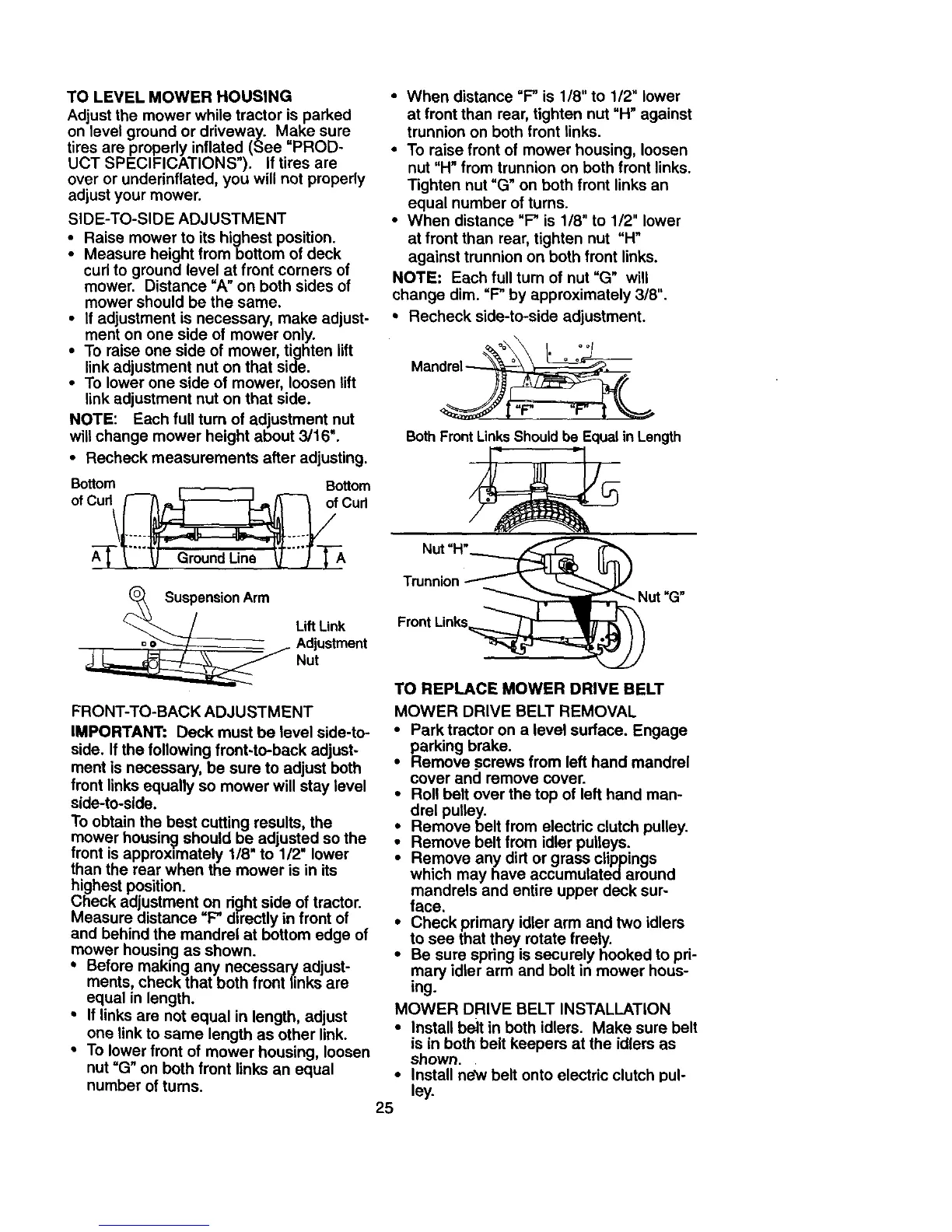
Check adjustment on d_]ht side of tractor.
Measure distance "F" directly in front of
and behind the mandrel at bottom edge of
mower housing as shown.
• Before making any necessary adjust-
ments, check that both front links are
equal in length.
• If links are not equal in length, adjust
one link to same length as other link.
• To lower front of mower housing, loosen
nut =G" on both front links an equal
number of turns.
• When distance =F" is 1/8" to 1/2" lower
at front than rear, tighten nut "H" against
trunnion on both front links.
• To raise front of mower housing, loosen
nut "H" from trunnion on both front links.
Tighten nut "G" on both front links an
equal number of turns.
• When distance "F" is 1/8" to 1/2" lower
at front than rear, tighten nut "H"
against trunnion on both front links.
NOTE: Each full turn of nut "G" will
change dim. "F" by approximately 3/8".
• Recheck side-to-side adjustment.
| r" r | L
Both Front LinksShould be Equal in Length
Nut "H"____'_
Trunnion X_Nu t "G"
Front Links_
TO REPLACE MOWER DRIVE BELT
MOWER DRIVE BELT REMOVAL
• Park tractor on a level surface. Engage
parking brake.
• Remove screws from left hand mandrel
cover and remove cover.
• Roll belt over the top of left hand man-
drel pulley.
• Remove belt from electdc clutch pulley.
• Remove belt from idler pulleys.
• Remove any dirt or grass clippings
which may have accumulated around
mandrels and entire upper deck sur-
face.
• Check primary idler arm and two idlers
to see that they rotate freely.
• Be sure spdng is securely hooked to pri-
mary idler arm and bolt in mower hous-
ing.
MOWER DRIVE BELT INSTALLATION
• Install be_t in both idlers. Make sure belt
is in both belt keepers at the idlers as
shown.
• Install new belt onto electric clutch pul-
ley.
25