3242 - 2-56 x ½” SH
3233 - Plastic Ride Height
Spacers 3, 4, 5mm
3246 - Delrin
Pivot Ball
CRC Pro-Strut
Front End
3242 & 1472 -
2-56 Red Locknut
1429 - 4-40 x 7/16” FH
1 - Pop the delrin pivot ball into the lower arm. Place the arm on a strong table and push the ball in
with the back of screwdriver handle. Or preferably, you can use CRC’s 4279 Ball popper pivot ball
tool. Notice the “lip” of the delrin pivot ball is pointing upward. The diagram to the left represents a
right side lower arm. For the left side, flip the second arm over and be sure the pivot ball is installed
with the lip again facing up.
2 - Once the ball is popped in, insert the black 2-56 clamp screw through the horizontal hole in the
lower arm. Thread the 2-56 red locknut onto the black screw. Tighten the screw slowly continuously
checking the pivot ball. When it begins to bind a bit, back the 2-56 screw off a bit. The ball should
be free to pivot with just a bit of drag. There is no need to have this ball super loose and free, a
slight drag will be just the right amount of clamping force.
Check this fit after a few runs as the ball will wear and require additional clamping force.
Lip
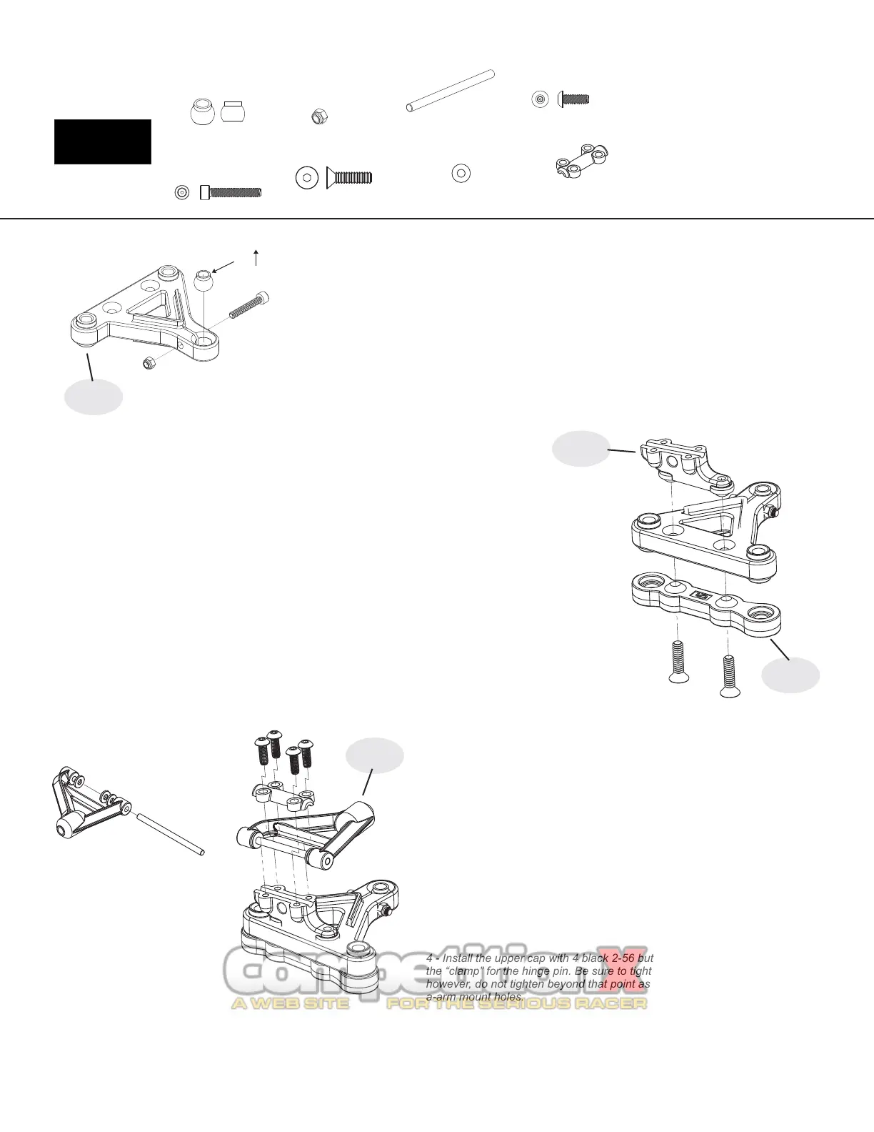
1 - Install the upper A-arm mount with the amount of Dynamic Caster desired. The options are 0, 5 and 10
degrees. The part shown to the right in the diagram is the 5 degree version, however it is most common to use
0 degree blocks for oval racing. The 10 will angle down more toward the front of the car, and the 0 will be
parallel to the chassis. The general thought is the more Dynamic Caster, the more steering the car will have at
corner entry.
2 - Use the 5 mm thick ride height block for 1/10th scale tires. For fine front ride height adjustments, use the
CRC #4262 optional front shim set. This set contains .010, .020 and .030” plastic ride height shims. After
selecting the proper spacer, push the 4-40 x 7/16” screw through the plastic ride height spacer, then through
the lower arm, and then thread the screw into the upper A-arm mount. Be sure NOT to over tighten. Just snug,
you are threading a metal screw into the plastic upper A-arm mount.
Bag F
3247
7
1 - Break the mold tree from the upper A-arm. You can clean up the mold
gates with a hobby knife or rotary tool.
2 - Locate the upper arm hinge pin and slide it into one half of the upper
arm. Locate 3 small caster shims. Push the hinge pin through the 3 shims.
Then continue to push the hinge pin all the way into the upper arm.
3 - Now, install the arm/pin/washer assembly onto the upper arm mount. Put
the hinge pin in the channel. At this point you can set your starting caster
setting by moving these washers forward and back. The position shown to
the left will result in a competitive handling. Moving them to the rear will
increase steering from the center and exit of the corner.
If the fit of the upper arm is tight, trim the upper arm mount SLIGHTLY with a
hobby knife.
4 - Install the upper cap with 4 black 2-56 button head screws. The topper is
the “clamp” for the hinge pin. Be sure to tighten so that any gap is gone,
however, do not tighten beyond that point as damage can occur to the upper
a-arm mount holes.
3245 - Hinge Pin
1253 - Caster Shim
3243 & 3230 -
Upper Cap
3247
3243
3254 - 2-56 Button Head
3247 - CRC Front Arm set
3243 - Upper Arm mnt set-0,5,10
3233
 Loading...