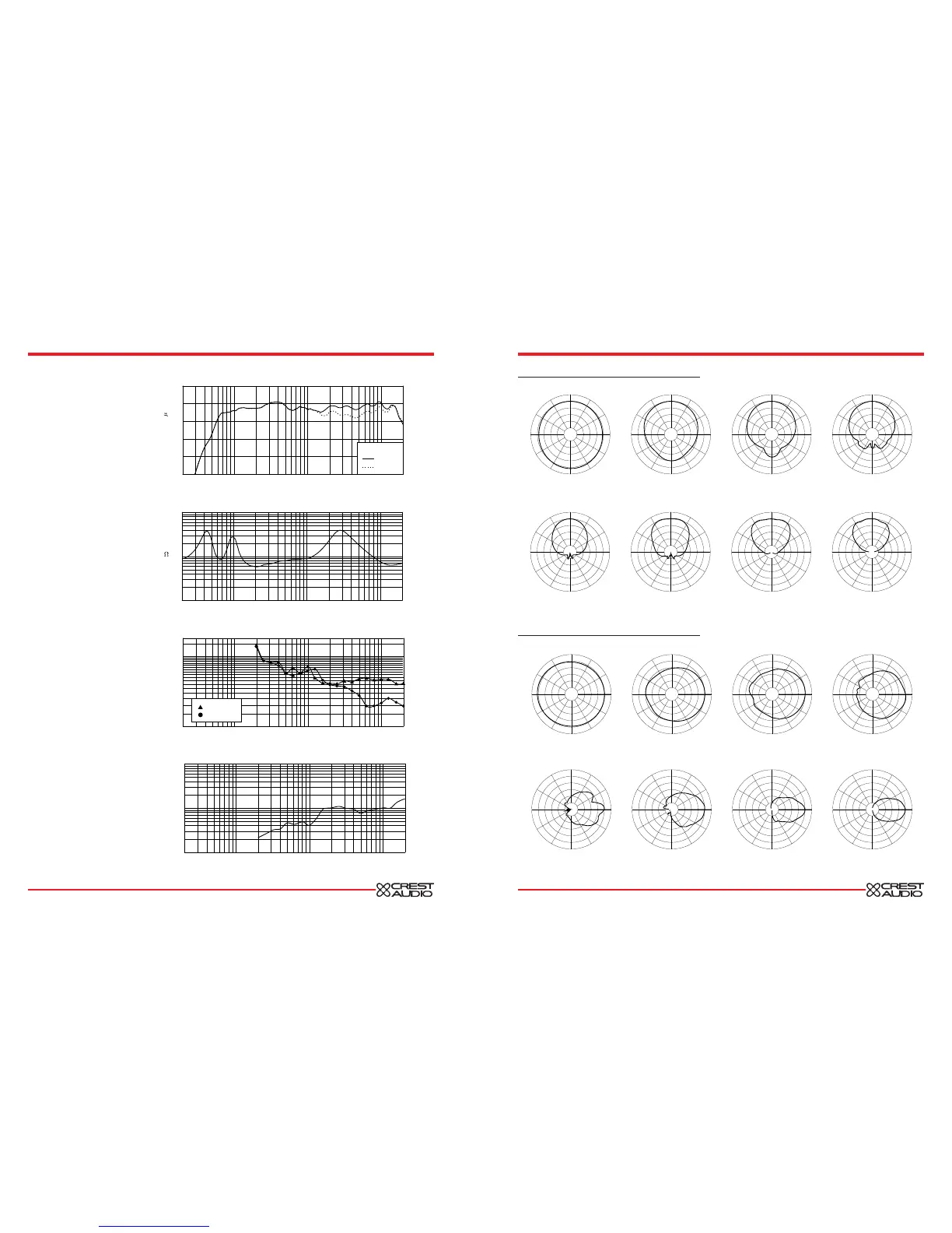
125 Hertz
250 Hertz
500 Hertz
1000 Hertz
2000 Hertz
4000 Hertz
8000 Hertz
16000 Hertz
125 Hertz
250 Hertz
500 Hertz
1000 Hertz
2000 Hertz
4000 Hertz
8000 Hertz
16000 Hertz
Power Handling
There are many different approaches to
power handling ratings. Crest rates this
loudspeaker system’s power handling
using a full-range form of the AES
Standard 2-1984. Using audio band 20
Hz to 20 kHz pink noise with peaks of
four times the RMS level, this strenuous
test signal assures the user that every
portion of this system can withstand
today’s high technology music. This rat-
ing is contingent upon having a mini-
mum of 3 dB of amplifier headroom
available.
Frequency Response
This measurement is useful in determin-
ing how accurately a given unit repro-
duces an input signal. The frequency
response of the Crest LQ 12 is meas-
ured at a distance of 1 meter using a 1
Watt (into the nominal impedance)
swept-sine input signal. As shown in fig-
ure 1, the selected drivers in the Crest
LQ 12 combine to give a smooth fre-
quency response from 76 Hz to 18 kHz.
Directivity
Beamwidth is derived from the -6 dB
points from the polar plots (see figure 3)
which are measured in a whole space
anechoic environment. Q and Directivity
Index are plotted for the on-axis meas-
urement position. These are specifica-
tions that provide a reference to the cov-
erage characteristics of the unit. These
parameters provide insight for proper
placement and installation in the chosen
environment. The blending of the com-
ponents of the Crest LQ 12 exhibit a
desirable beamwidth and directivity (fig-
ure 3 and 4) suitable for sound rein-
forcement applications.


 To Previous Page
 Loading...
