6 • DM-NVX-36x(C) Encoders/Decoders Product Manual – DOC. 8879C
DM-NVX-363C and DM-NVX-360C
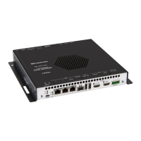
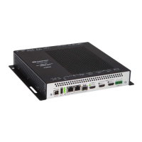
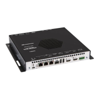
The following illustration shows the connectors, controls, and indicators that are
available on the DM-NVX-363C and DM-NVX-360C.
NOTE: The DM-NVX-363C and DM-NVX-360C contain the same connectors, controls,
and indicators. For illustrative purposes, only the card named DM-NVX-363C is
shown below.
DM-NVX-363C
OL and NV LEDs: Green OL LED indicates that the device is online with a control
system.
Green NV LED indicates that the device is encoding (transmitting) or decoding
(receiving) network video.
TX and RX LEDs: Green TX LED indicates that the device is in transmitter (encoder)
mode.
Green RX LED indicates that the device is in receiver (decoder) mode.
USB DEVICE: USB 2.0 Type-C™ connector, female;
USB 2.0 device port;
USB signal extender port for connection to a computer or other USB 2.0 host
1
Ethernet 1: 8-pin RJ-45 connector, female;
100BASE-TX/1000BASE-T Ethernet port;
Green LED indicates Ethernet link status;
Flashing amber LED indicates Ethernet activity
Ethernet 2: 8-pin RJ-45 connector, female;
100BASE-TX/1000BASE-T Ethernet port;
Green LED indicates Ethernet link status;
Flashing amber LED indicates Ethernet activity
Ethernet 3: 8-pin RJ-45 connector, female;
100BASE-TX Ethernet port;
Green LED indicates Ethernet link status;
Flashing green LED indicates Ethernet activity;
Amber LED indicates 100BASE-TX link status
1
The USB DEVICE and USB HOST ports cannot be used simultaneously.
 Loading...