CE 4000
Power Amplifi er
Operation Manual
page 11
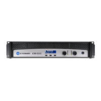
4 Operation
4.2 Front Panel Controls
and Indicators
A. Power Switch
Amplifi er is on when the switch is in the
“I” position.
B. Cooling Vents
Front-to-rear forced airfl ow.
C. Power Indicator
Green LED indicates amplifi er has been
turned on and AC power is available.
D. Signal Indicator
Green LED illuminates to indicate the pres-
ence of signal at the corresponding chan-
nel’s input. One per channel.
E. Clip Indicator
Red LED illuminates when the channel’s
output signal is being overdriven. One per
channel.
F. Fault Indicator
Red LED illuminates when the correspond-
ing channel is in protect mode. Also illu-
minates briefl y during normal power-up
when amplifi er is fi rst switched on. One per
channel.
G. Level Control
Rotary detented level control, one per
channel.
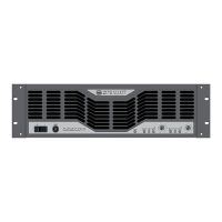
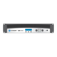
Figure 4.1
Front Panel Controls and Indicators

 Loading...