English
3
English
4
5. Operating Instruction
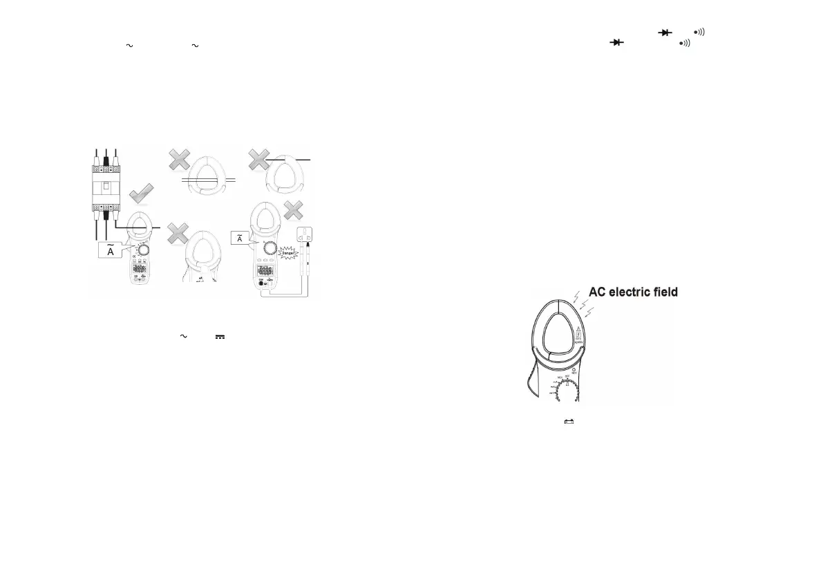
5-1. AC Current Measurement
CT44053 have two ranges:
400/600A and 2/20A.
(1) Set the Rotary Function and switch to the range needed.
(2) Press the trigger to open the transformer jaws and clamp them onto the one
conductor under test, and then take the reading on the LCD display.
Notes:
1. Do not loosen the trigger in a sudden to avoid the reading changes.
2. Do not clamp two conductors with the converse current direction to avoid the current
counteract with each other.
3. Keep the fingers under the arc-shaped part of the clamp to ensure safety
5-2. AC and DC Voltage Measurement
The most input voltage is 600V.
1) Switch Rotary Function at desired“
V” or“ V” position.
2) Inset the red test lead in“ ” terminal and the Black test lead in “COM” terminal for DC
Voltage measurement. In the AC Voltage measurement, insert the any test leads in“ ”
and “COM” terminal.
3) Insert the red and black test leads in the positive (+) and negative (-) sides of the circuit
under test respectively in the DC V measurement.
5-3. Resistance Measurement
1) Don’t use the instrument on the energized circuit. Set the
R
otary Function Switch to
“ ”position.
2) Insert the re
d test lead in “ ”terminal, And the black test lea
d
in “COM” terminal.
3) Read the measure result directly from LCD display
Note:
*
When measurement resistance value which more than 10MΩ, must be read display value
immediately in 1 - 2 seconds.
*
5-4. Diode & Continuity Check
1) Set the Rotary Function Switch to the position having and .
2) Press the “FUNC” key to change to diode or continuity .
3) In the Continuity mode, insert the test leads in the both ends of the conductor under tes
t.
The buzzer sounds, if the resistance under test is 50Ω or less.
4) Insert the red test lead in “ ” terminal and the black test lead in ‘COM” terminal to detect
the diode.
5) Insert the red and black test leads in the positive and negative of the diode under test
respectively. Read measure result on the display, which is the positive voltage drop of the
diode. If the test pens connect the converse polarity of the diode and ‘OL’ is shown on the
screen, that means the diode is OK.
5-5. NCV Function( “EF” is shown when there is no measuring)
Red LED on the right upper area on the panel quickly flashing when Electric field exceeding is
detected by the inductive sensor installed in the jaws. It indicates a presence of voltage in an
electrical circuit or equipment without touching them.
6.
7.
Maintenance
1. When the low battery symbol
is shown on the screen. It need to take off the back cover
and change the battery of the same model immediately.
2. Do not use abrasives or solvents on the meter. Clean it using a damp cloth and mild
detergent only.
3. When not in use for a long time, please remove the battery, and avoid storing in high
temperature and humidity.
Accessories
Test Leads: 1set
Battery: 1.5V AAA Type x 2pcs
User’s Manual: 1pcs
Carrying Case: 1pcs
V/Ω
Ω
When measuring low resistance, consider the contact resistance of the probe (about
0.2Ω-0.3Ω), first short-circuit the probe (i.e. the stylus of the two probes are in direct
contact), write down the resistance of the contact resistance on the display, and then
subtract the contact resistance of the probe from the measured resistance.
V/Ω
V/Ω
V/Ω
1)Set Rotary Function Switch to the “NCV” position.
2)When the clamp jaws detect voltage (Power stripe or anywhere with strong electric field)
the NCV LED is quickly flashing and there is buzzer. The more close to the electric field, the
frequency of the flashing and buzzer is quicker. According to the strength of the electric field,
it changes from “-” to “----”
3)This position can also be used to identify the live wire . The live wire can make continuous
flashing and buzzing with black or red test lead inserted at random. (Note:there could be of
mistake when there is LED light in the socket)
Note:
* The AC electric field is only in the placed shown in the picture below and no in the left clamp.
 Loading...